High voltage Voltage Transformer (PT)
TYD-110、138、220、245 single-phase series type voltage transformers, which meet the requirements of IEC 61869-5:2011
Share This Product:
  • PRODUCT DETAILS
  • SWITCHGEAR INSTALLATION
  • INSTALLATION DIMENSIONS
  • SWITCHGEAR STRUCTURE

Technical characteristics of the product

  • The capacitor voltage transformer(hereinafter referred to as transformer), which adopts advanced fast saturable reactor damping technology,''。" shape iron core technology and reasonable parameter design, is able to rapidly and effectively inhibit the lasting occurrence of the phenomenon of ferromagnetic resonance. In addition, the transient response characteristic of the transformer has reached advanced level in the world. The residualvoltage of transient response decreases to below 5%, which can meet the requirements of fast relay kee ing device. Furthermore, the residual three-phase open delta voltage is kept below 1 V, which makes the performance more reliable. Solid and liquid dielectric with good electric insulation performalnce are selected. Combining reasonable parameter design and advanced vacuum pumping and oiling technology for every transformer alone, the capacitor has excellent partial discharge performance,low loss and reliable quality. The product has a complete hermetic structure,and maintenance is unnecessary under normal operation conditions.

Application and applicable scope

  • Application

  • In high voltage and extra high voltage electricpower systems with a frequency of50 /60Hz,the transformer can be used for voltage measurementpower measurement, automatic control and relay protection. In addition, the product can be used as coupling capacitor in carrier coupling devices of power line.

  • 2.Applicablescope

  • The transformer is outdoor device. The ambiernt air temperature of the area for installation and operation shall be -40〜+45°C;the altitude shall not exceed 2,000 m (if the altitude is above 2,000 m, the product can be customized in accordance withuser's requirements after negotiation is performed between user and the factory); the wind speed shallnot exceed 150 km/h; the earthquake intensity shall not exceed 8 degrees; and there shall be no serious dust, vibration and bumpiness.

Type and main technical parameters

  • The meaning expressed by the letters and numbers in the type of transformer is as below:

  • For example:

Main technical parameters

  • The transformer can operate for a long term under the voltage that is 0.8 ~ 1.2 times of nominal voltage, and the transformer used in system with effectively earthed neutral can operate for 30 s under the voltage that is 1.5 times of nominal voltage. The transformer used in system with non-effectively earthed neutral that can not automatically eliminate ground failure can operate for 8 h under the voltage that is 1.9 times of nominal voltage.

  • The connection group of medium voltage transformer winding is l/l/l/l -12-12-12 or 1/1/1 - 12 -12.

  • The creepage distance of the transformer whose type has "H" is 2 25 mm/kV; See the annotation Testing Records for Delivery of Capacitor Voltage Transformer for the special requirements on creepage distance.

  • See table 1 for the insulation level of transformer, and see table 2 for the profile parameters of transformer.

  • See table 3 for correct grade of transformer, the corresponding Voltage error, phase angle difference and working conditions.

  • The capacitance deviation between carrier coupling capacitance of capacitor divider C, high- voltage capacitance Ci and medium-voltage capacitance C2 shall not exceed -5% ~ + 10% of the nominal value; and the deviations of Ci and C2 shall not exceed 士 5% of their errors.

  • The tangent value of dielectric loss angle of capacitor divider shall not exceed 0.0015.

  • The transformer meets the requirements of GB/T4703-2007 Capacitor Voltage Transformers, GB/T 19749-2005 Coupling Capacitors and Capacitor Dividers, JJG 314-94 Voltage Transformers for Measuring Service, IEC 61869-5:2011.

  • The nominal voltage, nominal capacitance, precise grades and secondary burden of transformer shall be selected properly, so as to meet the use demands.


Table 1 Insulation level of transformer

Primary nominal voltage of transformer

35/而

66/73

110/V3

220/<3

330涌

500冲

Nominal voltage of system

35

66

110

220

330

500

Highest voltage of system

40.5

72.5

126

252

363

550

Power-frequency withstand voltage (effective value) 1 min

80

160

230

460

510

740

Lightning impulse withstand voltage (peak value) 1.2 / 50 us

185

• 350

550

1050

1175

1675

Nominal operation impulse withstand voltage (peak value) 250 / 2500 u s

950

1175

Table 2 Profile parameters of transformer

©NEWS

Type

Dimension W1XLXH mm

Installation size W2XL1 mm

Weight kg

Drawing No.

1

TYD35/V3-0.01HF

0550X710X1260

4-0 25
395 X 395

385


Drawing 2

2

TYD35/S-0.02 HF

3

TYD66/V3-0.01 HF

0550 X710X1890

455

4

TYD66/V3-0.02HF

590

5

TYD110/V3-0.007H

455

6

TYD110/V3-0.01 H

455

7

TYD 110/^/3-0.015 H

590

8

TYD110 沌-0.01 H

0600X760X2000

4-0 25
458 X 458

525

9

TYD110/V3-0.02H

590

10

TYD220/诟-0.0035 H

0550X710X3220

4-0 25
395 X 395

650


Drawing 3

11

TYD220/V3-0.005 H

650

12

TYD220/V3-0.0075 H

850

,13

TYD220/V3-0.01 H

0600X760X3330

4-0 25
458 X 458

850

14

TYD220/V3-0.02H

1180

15

TYD330/V3-0.005 GH

0565X740X4860

4-0 25
500 X 500

1270


Drawing 4

16

TYD500/由-0.005 H

*0565X740X6500

1620

17

TYD500/V3-0.01 H

Table 3 Working conditions of transformer and error limit


Item


Accuracy grades for measurement

Accuracy grades for protection

0.2

0.5

L0

3.0

3P

6P

Error limit

Voltage error (%)

±0.2

±0.5

±1.0

±3.0

±3.0

±6.0

Phase (')

±10

±20

+40

Undefined

±120

±240

Working conditions

Voltage (%)

80 〜120

5-150 (or 5-190)


Permitted frequency range (%)

99 〜101

96 〜102

Permitted temperature range

From the lower limit temperature to upper limit temperature

Burden (%)

25 〜100

Power factor of burden

0.8 (lagging)

Note: to the tre

the values in brackets is applicable msformer used in system with non-effectively earthed neutral

Operating principle and main structure

  • Operating principle

  • The voltage division of the transformer is performed by capacitor divider. Medium voltage transformer makes the medium voltage transformed into secondary voltage, so as to compensate the sum of reactance of reactor and leakage reactance of medium voltage transformer, and connect and resonate with equivalent capacitive reactance [l/s (C1+C2)] to eliminate the voltage change caused by the change of capacitive reactance voltage drop for secondary burden change, making the voltage stable

See figure 1 for the electrical schematic diagram

1. When the secondary winding of the transformer is double windings, lain is an, and there is no 2a2n terminal. And an additional 3a3n terminal shall be added.

2. When the N terminal of the transformer is connected to combined filter, the N terminal shall be disconnected with ground point; and it shall be connected to the ground point after it is connected to the combined filter.


Main structure

  • Capacitor voltage transformer, which has combined single pole structure, comprises capacitor divider and electromagnetic device. The capacitor divider comprises 1 〜4 series capacitors, and the high voltage terminal is at the top of the capacitor divider.

  • The medium voltage terminal A and low voltage terminal N of the transformer are led to the inside of the electromagnetic device through the bush on the bottom cover of the bottom capacitor to connect with the high voltage terminal A of medium voltage transformer and N terminal on outgoing line plate.

  • The electromagnetic device comprises medium voltage transformer, compensation reactor and the damping device inhibiting ferromagnetic resonance (they are inside oil tank). The secondary winding and carrier communication terminal are led out from the outgoing line terminal on the front surface of the oil tank. See figure 2 or figure 3 for the profile.

Hoisting and keeping

  • During packing, unbox, testing, installation of transformer and any other occasions needing hoisting, the capacitors must be hoisted singly. The transformer of above 220kV must not be hoisted by stacking above two capacitors (including two capacitors). The hoisting shall be stably performed by using the top sling provided by manufacturer or the lifting hook on the oil tank, so as to prevent the action of impact force (if the product oil tank has lifting hook, then the lifting hook shall be used for hoisting and balance shall be kept.).

  • The transformer shall be vertically fixed inside the packing box, and the transportation only can be performed after the packing is completed. During the process of transportation and storage, the transformer must be kept vertical, and collision and other mechanical damages shall be prevented. The transformer shall be stored in the places with a ambient air temperature of -25 〜+ 55 °C, and there shall be no fire goods, explosive substances, corrosivity and serious concussion.

Installation and debugging

  • The transformer shall be installed on firm horizontal base in accordance with the places stipulated under 2.2. Its connection with the base is performed through the 4 mounting holes on the base with embedded screw; fix the transformer with nut and washer (or fix the transformer by directly welding it with embedded iron block). When the capacitor is hoisted, the operation shall be performed according to the requirements under 5.1. Use the embedded screw, nut and washer attached to the transformer for the connection between capacitors.

  • The high voltage terminal at one side of the transformer is the terminal board of tbe top cover of capacity divider. The N terminal inside low voltage outgoing line box is provided for the connection with carrier coupling devices or the connection with "丄"(for normal earthing, the connection piece provided by manufacturer shall be used to directly connect the terminal with “ 丄";when the terminal is used for carrier communication, the terminal shall be connected to the carrier coupling device, and then disconnect the connection piece). The oil tank must be directly and firmly connected to ground. The electric connection of secondary circuit is performed through the secondary outgoing line terminal of the outgoing line box of the transformer.

  • The error for the capacitor divider and electromagnetic device of each delivered transformer is adjusted correspondingly, so the capacitor divider and electromagnetic device can not be changed with those of other transformers.

  • The interior of the “ 丄 M terminal inside the outgoing line terminal box has been connected to oil tank.

Use and safety

  • The working conditions of the transformer shall comply with the regulations under 2.2, 3.2.4 and 3.2.5.

  • If the transformer is used for carrier communication, the N terminal inside the outgoing line terminal box of the transformer shall be connected to ground through combined filter If the transformer is not used for carrier communication, the terminal must be directly connected to ground and open circuit is prohibited, or the insulation between terminals on the insulating plate inside outgoing line box will be damaged (which will further cause the damage of transformer),

  • After the transformer stops operation upon power off, the conducting parts shall be discharged

Maintenance

  • Testing is unnecessary for the transformer under normal operation conditions. Users are suggested to check the capacitance of capacitor divider and tangent value tg 5 of dielectric loss angle for each 5 years or longer time. During the check process^ the ambient air temperature shall be 25 + 10 °C, and the relative error of the equipment used for measuring capacitance shall not exceed + 3%, If the deviation between Ci, C2 and the actually measured values in Testing Records for Delivery of Capacitor Voltage Transformer- exceeds ± 10% or the tangent value tg 8 of dielectric loss angle exceeds 0.5%, the transformer use shall be stopped.

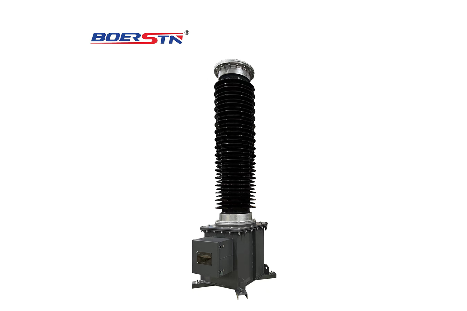
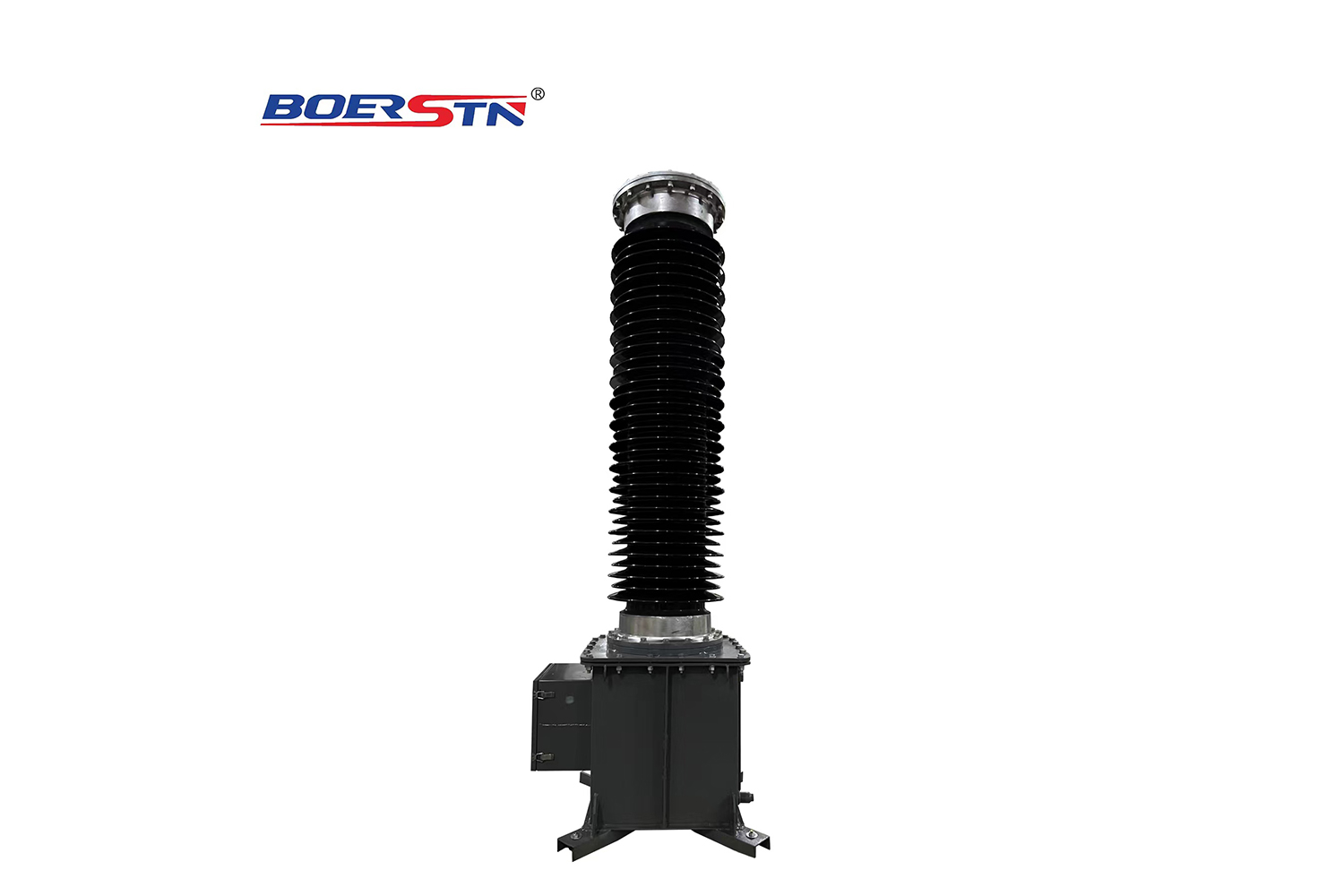
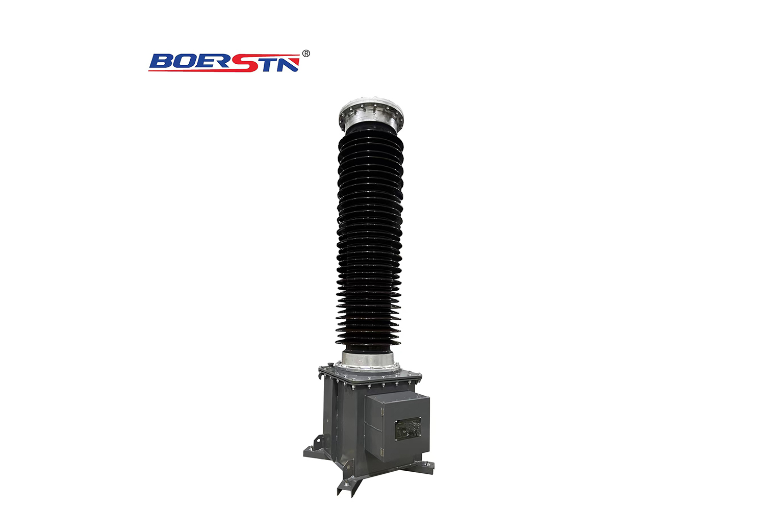
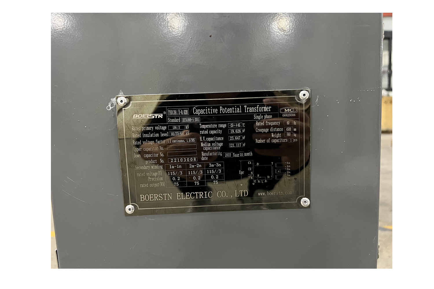
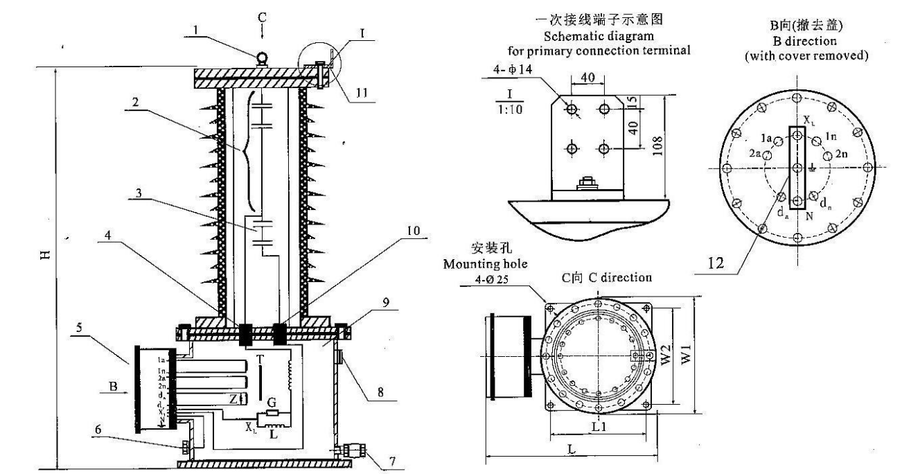
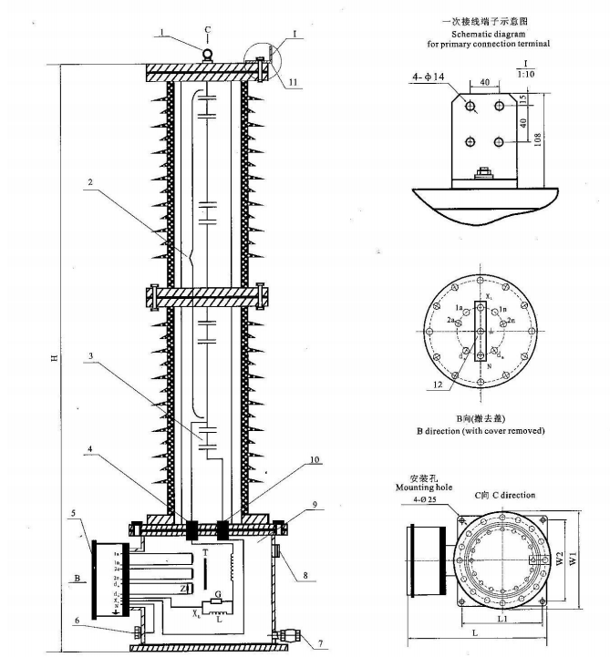
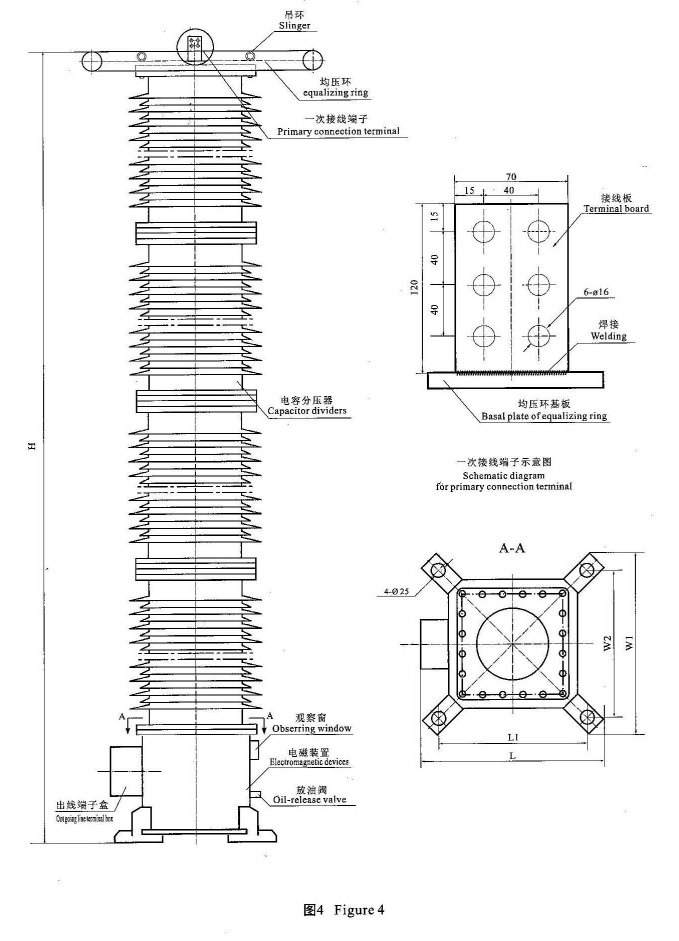
  • The transformer is completely sealed product with insulating oil inside. The sealing condition of the transformer shall be often checked during use process. The inspection parts include the joining between upper cover plate, lower cover plate and porcelain bush, the joining between outgoing line plate inside outgoing line terminal box and oil tank. The transformer shall not be used if there is oil leakage.

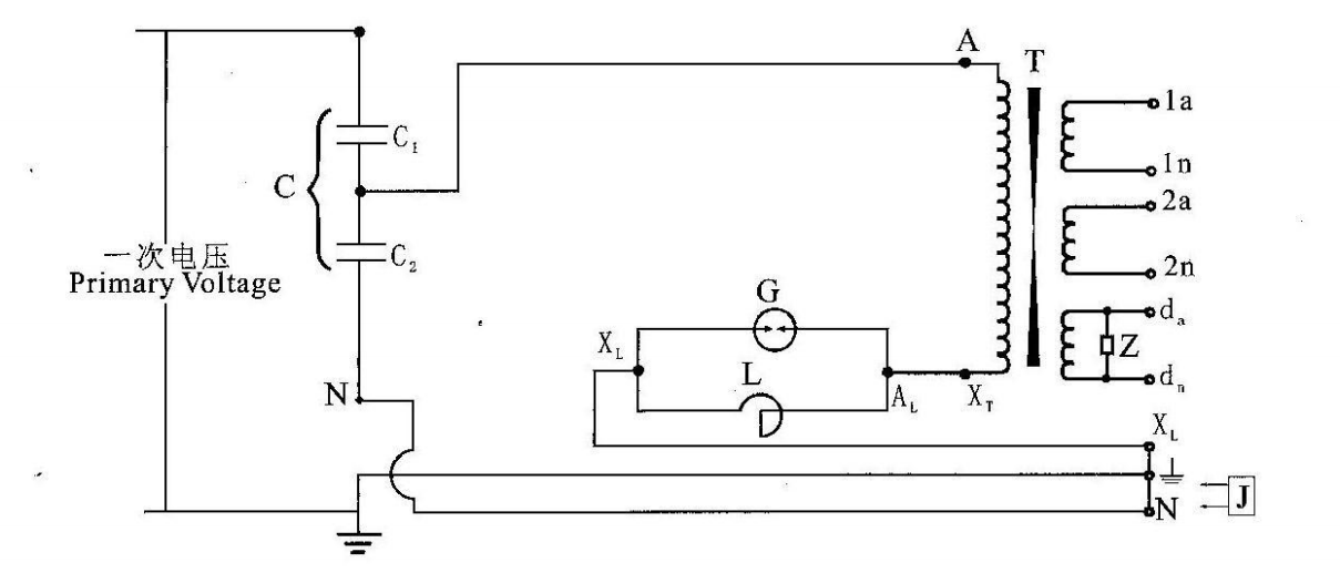
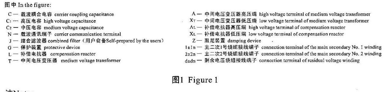
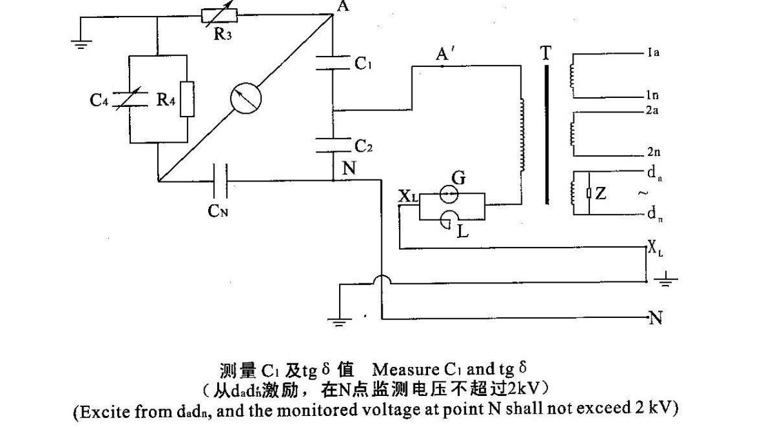
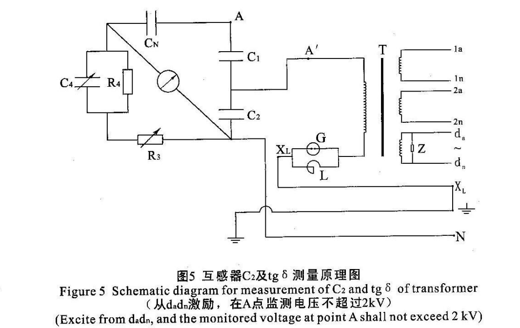
  • The electrical schematic diagram for measurement of capacitance and tg S i$ as figure 5. During measurement, carrier communication terminal N must be impending.

  • Self excitation method shall be used for measuring the capacitance and tg $ of capacitor divider. The excitation at the low voltage side of the medium voltage transformer can be used as testing power supply. At this time, the primary side voltage (point A or point N in figure 5) of medium voltage transformer shall be strictly monitored, so as to make the voltage not exceed the regulated value, or the parts and components in the electromagnetic device will be burned out. See figure 5 for the schematic diagram for testing.

  • Withstand voltage test for product only can be performed when necessary during acceptance and use process. For the voltage value used for test, the testing voltages for the low voltage terminal of capacitor divider, reactor and the secondary winding of the medium voltage transformer shall be the data listed in Testing Records for Delivery of Capacitor Voltage Transformer, and all the other items shall not exceed 70% of the corresponding values listed in Testing Records for Delivery of Capacitor Voltage Transformer. During the testing, the capacitor divider shall be separated with the electromagnetic device. The protective device in the electromagnetic device shall be taken off and the damping device shall be cut off. Then, voltage shall be respectively applied to the capacitor divider and electromagnetic device. Voltage must not be applied with the two connected, or the electromagnetic device will be damaged. Original status must be recovered after the testing is completed.

  • The transformer is completely sealed product. The capacitor divider and electromagnetic device must not be dismounted without the approval of the manufacturer,

  • Oil filtering or oil change is not necessary during the normal operation of the transformer. After oil sampling is performed, oil must be filled to the oil level before sampling, and 45# transformer oil can be used.

Common faults and troubleshooting method

  • The electromagnetic device of transformer has oil leakage phenomenon. Oil leakage of the oil tank generally occurs at the edge of outgoing line insulating plate inside outgoing line terminal box. The problem can be solved through screwing down the seal screws uniformly.

  • The N terminal on outgoing line insulating plate discharges to the earthed oil tank. The reason for burning out of outgoing line insulating plate is that the N terminal is not directly connected to tc x " when it is not used for carrier communication. At this time, the repair can not be performed on site, and the

Supply list for capacitor voltage transformer

  • See table 4 for the supply list fbr capacitor voltage transformer

Table 4 Supply list for capacitor voltage transformer


Serial NO.

Type

Number for each transformer


Appendix


Electromagnetic device (connected with the bottom capacitor)

pUpper one of capacitor divider

Connection piece


Packing box


User Manual


Stud


Nut


Elastic washer

Plain washer

1

TYD35

1


1

ssgulu.±n.b

2

TYD66

1


1

3

TYD110

1


1

4

TYD220

1

1

12

24

24

24

2

5

TYD330

1

2

24

48

48

48

3

6

TYD500

1

3

36

72

72

72

4

Remark: AH connection pieces to be mounted between the upper and lower section of the products of superposed type have already been mounted on the cover.


Feedback form contact with us
Related Product
145~252KV Hybrid Gas Insulated Switchgear (HGIS)
Overview 1. 1 ZHW-145 Hybrid Gas Insulated Switchgear (hereinafter referred to as HGIS) belongs to three-phase AC ...
LW36-72.5~252KV  Outdoor SF6 Circuit Breaker
LW36-72.5~252KV Outdoor SF6 Circuit Breaker
Summary LW Series self-energy SF6 Circuit Breaker is a three-pole/single-pole AC 50Hz/60Hz outdoor high voltage power transmission...
LW30-72.5~252KV Outdoor SF6 Dead Tank Circuit Breaker
Dead tank type SF6 Gas Circuit- Breaker 72.5kV up to 252KV, 25kA~63kA, 1250A~4000A for Outdoor Three phase/Si...
40.5~252KV GW7 Outdoor High Voltage Disconnector Switch
1.Application GW7-145D(W)series is a kind of three column ,horizontal/vertical,double break out-door three phases AC HV disconnect...
Product Catalog