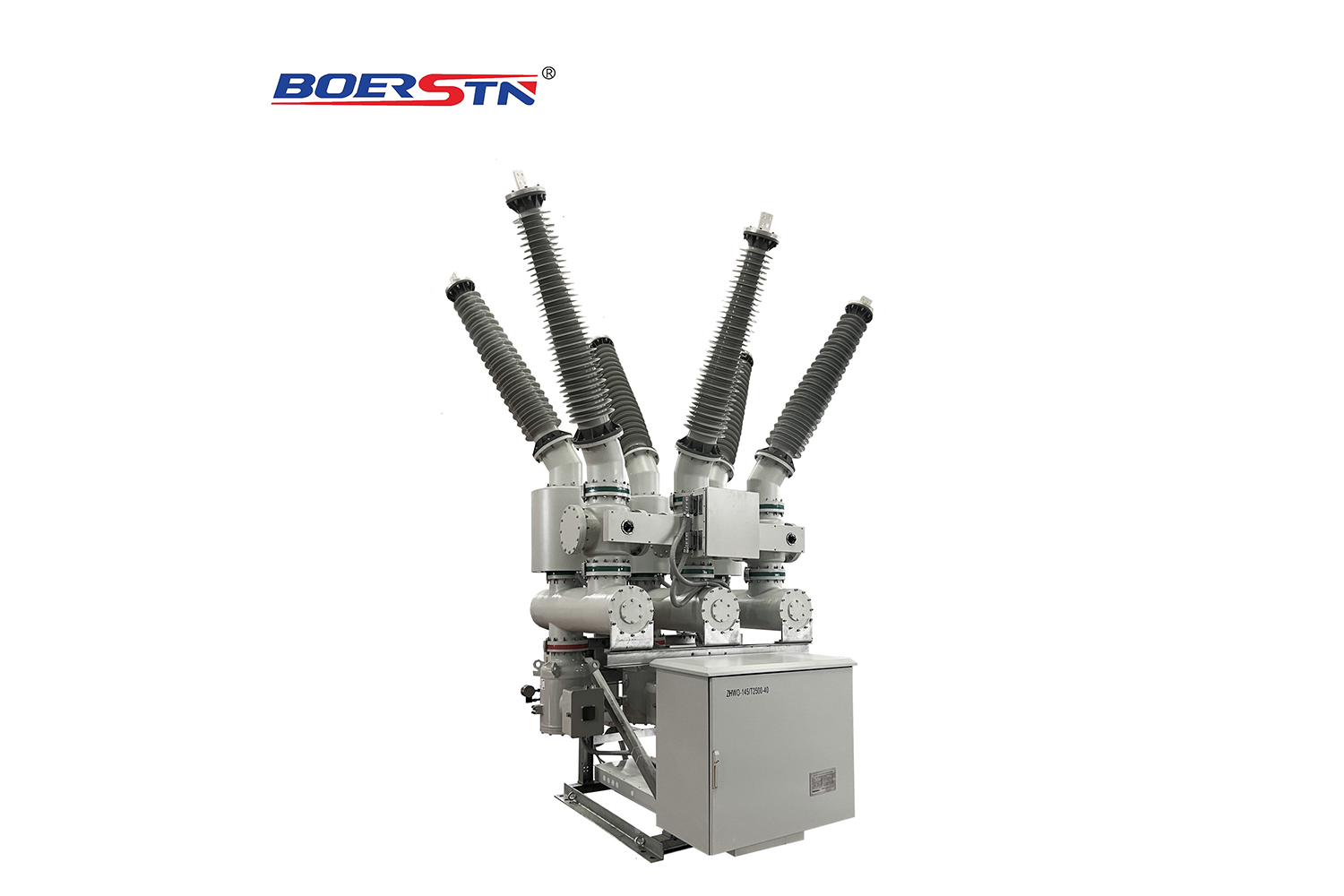
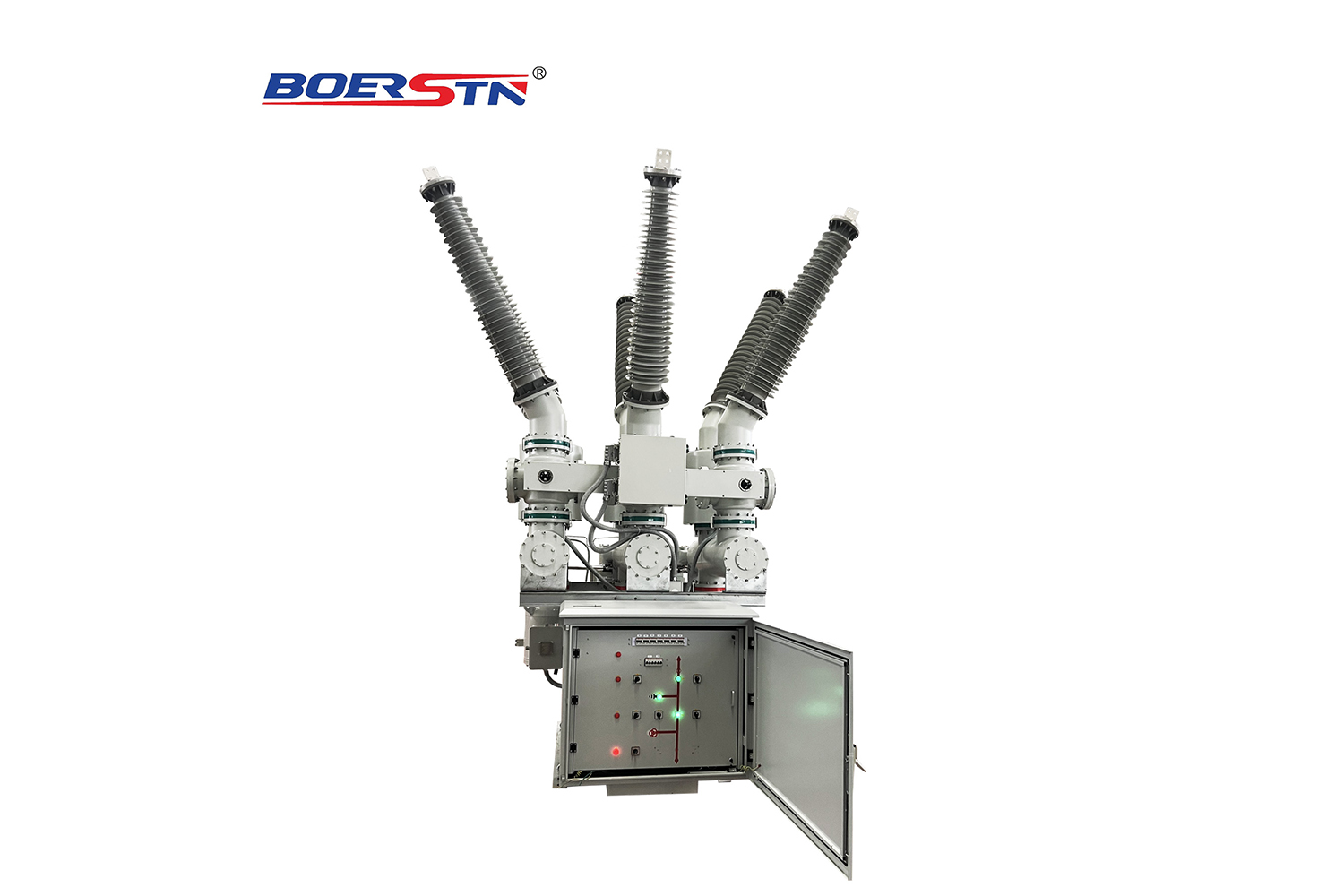
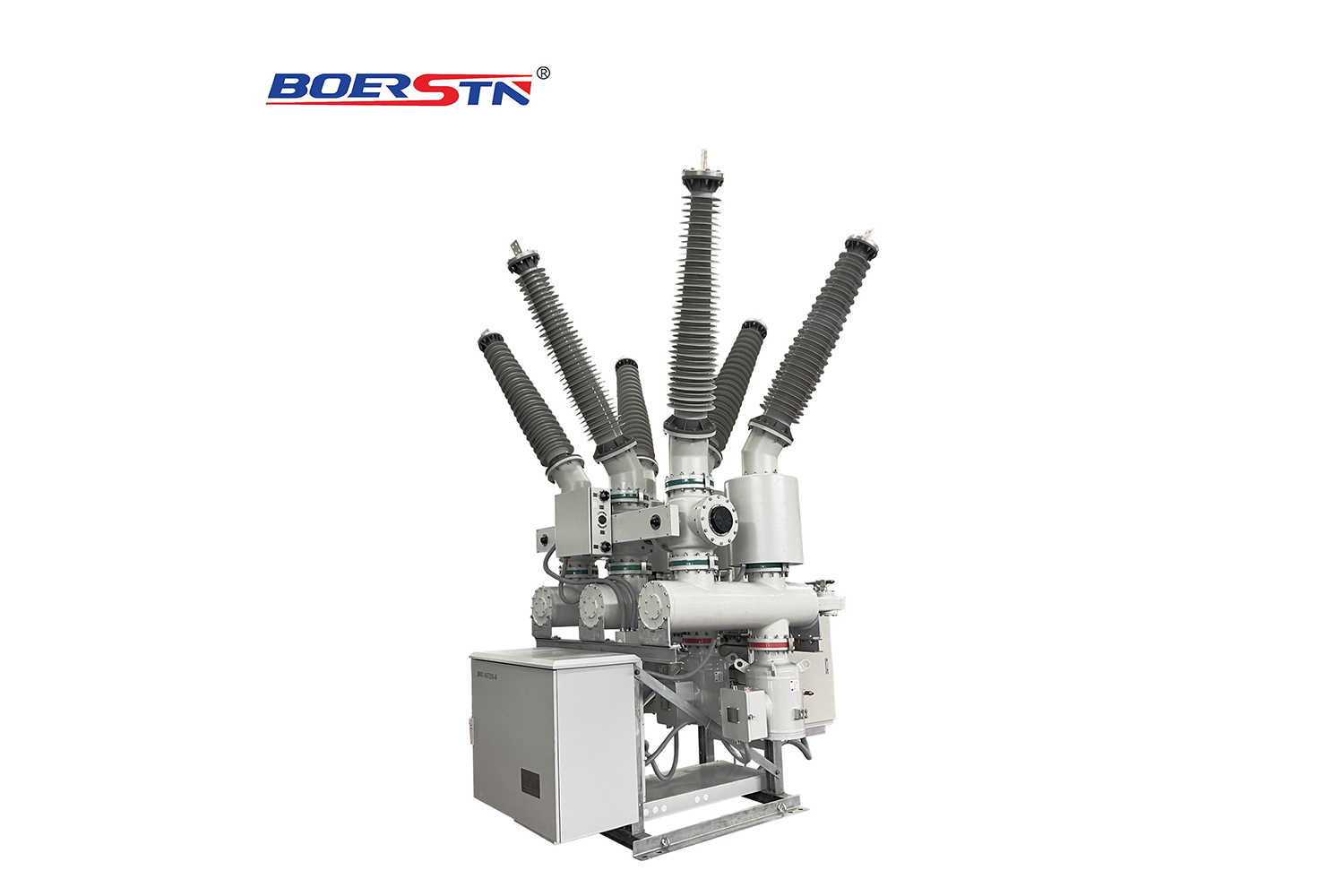
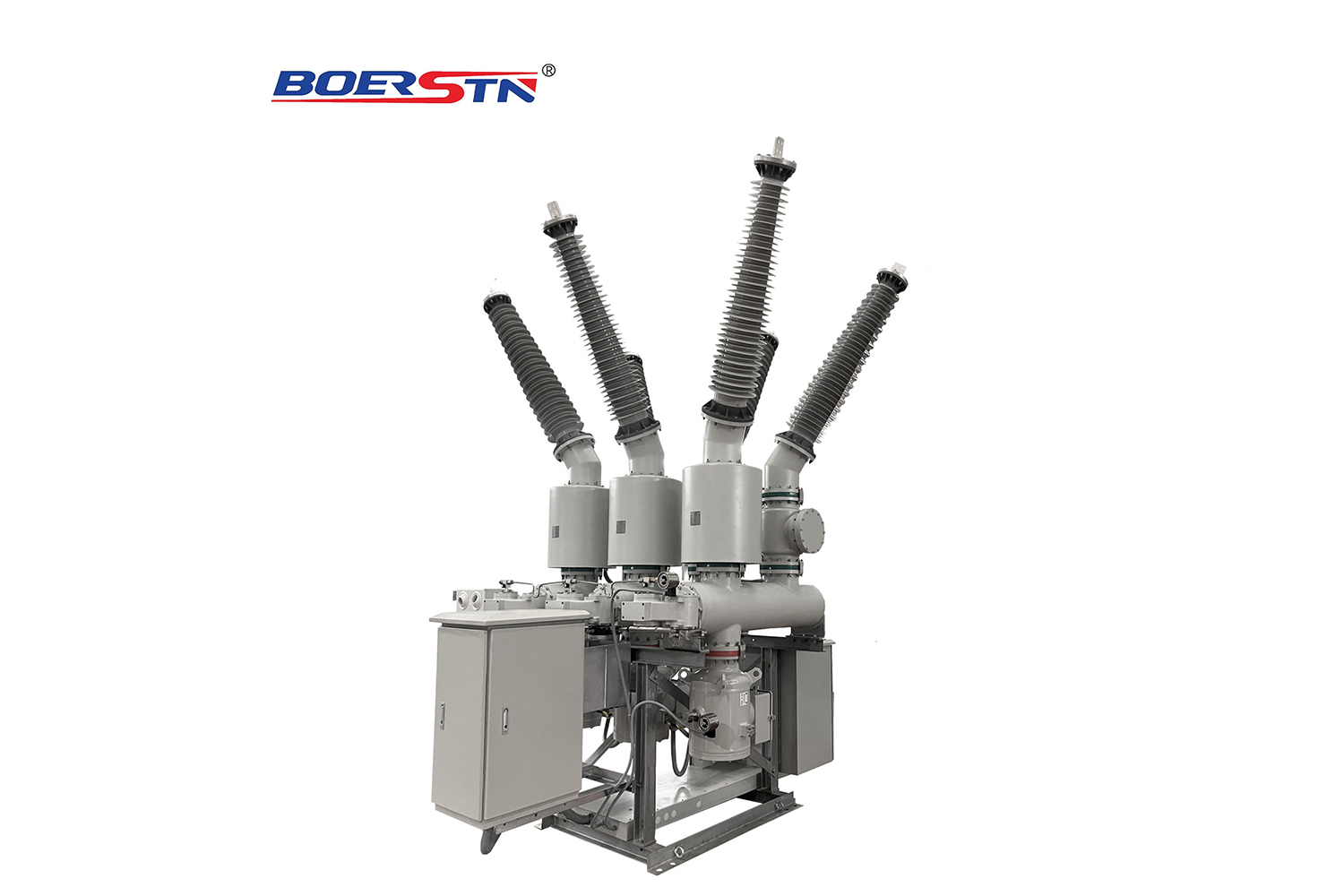
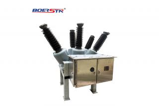
145~252KV Hybrid Gas Insulated Switchgear (HGIS)
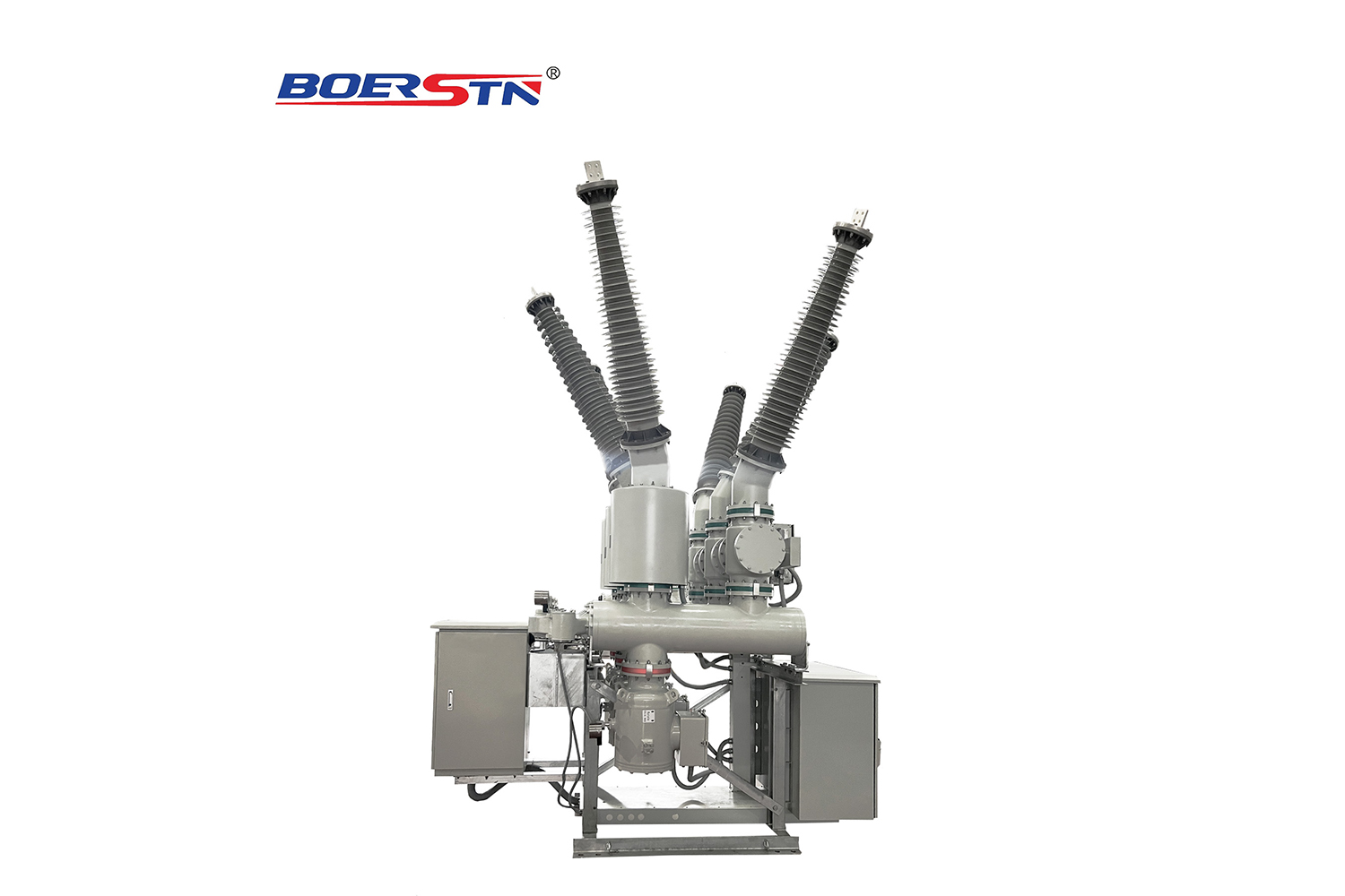
145~252KV Hybrid Gas Insulated Switchgear (HGIS)
Boerstn Electric Co.,Ltd is one of the toppest Hybrid Gas Insulated Switchgear in China.During these years of exporting , Boerstn Electric Co.,Ltd now has rich experience in the worldwide markets

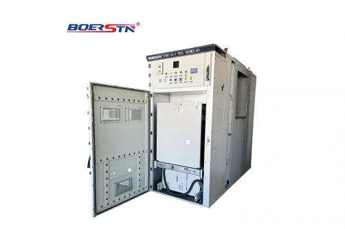
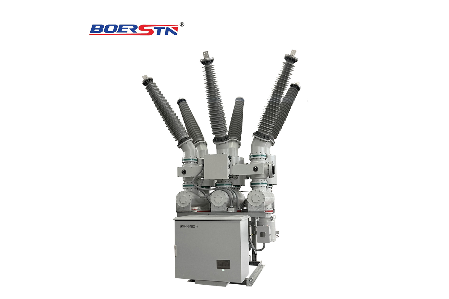
1. 1 ZHW-145 Hybrid Gas Insulated Switchgear (hereinafter referred to as HGIS) belongs to three-phase AC high-voltage transmission equipment and is in three-phase box type structure. The core part circuit breaker adopts self-energy arc-extinguishing principle equipped with the spring mechanism. It is applicable to 145kV electric system, and used to cut off the load current and fault current, convert and isolate lines, measure current and voltage, and protect overvoltage, etc. It assembles all the primary equipment in the substation within the grounding metal shell, except the power transformer, and then constitutes an integral as per the main wiring requirements of users, and then it is filled with SF6 gas as the insulation and arc-extinguishing medium. It connects to the external power grid via lead-out bushing or cable connection devices.
1. 2 When comparing ZHW□-145 HGIS with conventional power station, it has many advantages, such as small floor area, reliable operation, long repair cycle, excellent electrical properties, and no external influence. It is a popular high-voltage electrical product in urban power grid transformation and heavy pollution areas and highly reliable substations.
1. 3 GIS can meet the requirements of the national standard GB7674-2008 Gas Insulated Metal-Enclosed Switchgear with Rated Voltage of 72.5kV and Above, and the international standard IEC 62271-203: 2003 high-voltage switchgear and control equipment—Part 203 Gas Insulated Metal-enclosed Switchgear with Rated Voltage of 72.5kV and above.
1. 4 Operating environmental conditions a) Installation site: outdoor
b) Ambient environment: -40°C-+40°C;
c) Altitude: (merely for the lead-out bushing) ≦1,000m;
d) Icing thickness: 10mm;
e) Pollution grade: III and IV;
f) Earthquake intensity: AG5;
g) Wind speed: ≦34m/s;
h) Places without flammable, combustible, chemical corrosion and violent vibration.
1. 5 Safety and environment criterion
1. 5.1 Special explanation
1. 5.1.1 Before installing and using the equipment, please firstly read and fully understand the manual.
1. 5.1.2 Before installing and using GIS equipment, please carefully read the manual at first, to understand the regulations on safety, operation, installation and maintenance.
1. 5.1.3 All the size marks in the manual are international standard unit system or other equivalent unit systems.
1. 5.2 Safety regulations
Before installing and using GIS equipment, please carefully read the manual, to understand the regulations on safety, transportation, installation, operation and maintenance. Please pay attention to the parts marked with dangerous, warnings, cautions, notice and safety instructions, etc.
These words remind the reader that those marked places contain important safety information, and must be carefully read, to ensure the safety and valid operation of product unit. “Dangerous” indicates places with emergency danger, and in case of failing to follow the regulation, it may cause death or serious personal injury. “Warnings” indicates places with potential danger, and in case of failing to follow the regulation, it may cause death or serious personal injury. “Cautions” indicates dangerous places, and in case of failing to pay attention to the avoidance, it may cause slight personal injury or property loss. Please pay attention to the help information. It is requested to conduct the equipment installation, operation and maintenance in accordance with the relevant regulations and existing safety regulations. Only personnel with certain qualification can obtain authorization, and one qualified operating personnel must:
(1). Carefully read the manual;
(2). Get familiar with the equipment installation, structure or operation, and clearly know about the dangers thereof;
(3). After training and authorization, they shall be capable of safely conducting closing, opening, grounding, unlocking and circuit recognition as per the safety operation methods confirmed thereby;
(4). Be responsible for equipment service, maintenance or repair after training and authorization;
(5). After training, they shall be capable of correctly maintaining and using protective equipment as per the safety operation methods confirmed thereby, such as: insulation, gloves, safety helmet, protective glasses, protective mask, and fireproof suit;
(6). Pass emergency rescue training.
DANGEROUS
1. In order to prevent electric shock from burning or hurting others, when the equipment is electrified, do not touch the circuit facilities or wiring terminals. Even if after the equipment is turned off and isolated from the power supply, non-professionals are prohibited from touching the wiring terminal or porcelain bushing, because they may still have residual charge.
2. Under pure state, SF6 is colorless, odorless, non-toxic and incombustible inert gas. When the air we breathe has sufficient oxygen, SF6 is safe, and will cause no damage to the ecological system, but the air in the gas chamber that has been operated and generated electric arc will generate toxic substances, so it shall be recycled during the repair.
WARNINGS
1. In order to prevent falling damage, except for professionals conducting equipment inspection, it is prohibited from climbing, sitting, leaning, or standing on GIS equipment.
2. Do not remove the bypass line or wiring terminal of the equipment, otherwise it will cause the electric shock, burning or death of personnel. When the bypass line or wiring terminal must be removed for maintenance or repair (must be professional maintenance personnel), it is requested to ensure that the main circuit power supply disconnects, and the grounding line or capacitance is adopted. After completing the maintenance and repair work and before transmitting power to the main circuit, reliably install the bypass pole and grounding terminal.
3. Do not enter the breaker arc-extinguishing chamber, unless it has been confirmed that the internal environment has good ventilation and contains at least 18% oxygen. Since the breaker arc-extinguishing chamber is filled with SF6 gas under normal conditions, in case that the oxygen content and ventilation conditions thereof are uncertain, working personnel will be subject to dyspnea and even suffocation due to the unpleasant smell.
4. In order to prevent the damage incurred by the fast release of SF6 gas, do not loosen the air release valve of the pressure accumulator; if so, it will cause the eruption of high-pressure SF6 gas (at least 14MPa) or other parts via the release of internal gas pressure.
5. Except for professionals, do not loosen or open GIS door/cover plate under the repair/emergency conditions. When the door or cover plate is opened, professionals shall not touch the inner elements of the equipment, because they may have residual charge; during the maintenance period, it will still cause the damage of hands or other body parts as well as the personnel inside the unit, in case of careless startup via remote control.
6. In order to prevent the burning or other personal injury incurred by electric shock, when GIS equipment is in operation, no one shall touch the low-voltage or high-voltage electrified circuit.
7. Do not enter GIS gas chamber, unless you have affirmed that SF6 gas has been eliminated inside, with excellent ventilation, and the oxygen content shall be bigger than 18%. Unsmooth ventilation or insufficient oxygen will cause unsmooth respiration and even suffocation.
8. In order to avoid the damage incurred by the fast release of gas pressure, when the equipment is running, please do not release the bolt of any airtight parts of GIS; otherwise it will be subject to the damage incurred by the displacement of bolts and other components during the release of gas pressure.
9. In order to prevent the equipment damage and personal injury incurred by falling, please do not stand on or lean against the gas piping and the cable bridge of the equipment.
CAUTIONS
1. Since GIS is a set of complicated and huge unit structure for power supply, it is prohibited from climbing or standing on unstable platforms for operation. Climbing operation must be fastened with safety belt; besides, it is also requested to check whether the climbing framework and escalator are secured.
2. Under the condition of no gloves, do not directly contact the heater of the control cabinet. Since the heater is in high temperature, which will cause burning.
Notice
1. In order to avoid accidents, firstly confirm that the control cabinet and all the relevant equipment can only be repaired under cutoff and fully uncharged status.
2. When it is about to repair GIS unit, firstly confirm that the gas pressure inside the unit has been fully released, and then disassemble the cover plate and end cover. If the unit still has pressure inside and the cover plate and end cover have been loosened, it may cause personal injuries because the connection bolt and other parts will be moved during gas release.
3. In order to prevent water or other reasons from bringing humidity, please keep all the cabinet doors and observation panels of GIS control cabinet in closed and safe locking status.
4. In order to prevent the damage of surface of operating mechanism box (humidity invasion will also cause damage), please do not climb or lean against any part of the operating mechanism box.
5. In order to ensure appropriate gas pressure, when GIS is running, please do not open or close any valve.
6. In order to prevent air leakage, please do not loosen GIS or any piping bolt, and it is requested to close the upper cover of GIS.
7. Do not stack the current transformer units one by one. Since all of them are quite heavy, with solid shell, it may cause abrasion when stacking. Moreover, the current transformers vertically stacked thereby may cause personnel injury and death once loosening and displacement occur.
8. It is strictly prohibited from putting down the current transformer. If the current transformer unit is put down, it may cause equipment damage, and may also cause personal injury.
9. Do not install any damaged CT unit, and after installing one damaged CT unit, it will cause the damage to surrounding equipment and the personal injury.
10. It is prohibited from carrying CT unit without adopting the mode recognized by the manufacturer. Since each CT is quite heavy, with solid shell, if one unit is fallen, it may cause the damage of current transformer, or personal injury and death.
11. In order to prevent electric shock from causing the burns or other injuries of the working personnel, except for authorized maintenance personnel and equipment operating personnel, no one is allowed to touch or get close to the current transformer (CT).
12. The current transformer (CT) shall not be operated above the rated current stipulated by the manufacturer. When operating CT unit above the rated current, it may cause the overheating of equipment and even fire.
13. In order to prevent electric shock from causing the burns or other damages of the working personnel, when current transformer (CT) is running, no one is allowed to touch the low-voltage circuit.
14. In order to prevent electric shock from causing the burns or other damages of the working personnel, when the current transformer equipment (CT) is running, do not remove or disconnect any secondary terminal.
15. In order to prevent electric shock from causing burns or other personal injury accidents, during PT equipment operation, please do not unfasten the connection point between the neutral point of the primary coil and the ground potential.
16. In order to prevent electric shock from causing burns or other personal injury accidents, when operating GIS equipment, please do not disassemble PT from GIS.
17. In order to prevent PT damage or accidents, when PT equipment is running, please do not cause the short circuit of PT secondary wiring terminal with wires.
18. In order to prevent electric shock from causing burns or other personal injury accidents, when PT equipment is running, no one is allowed to touch the low-voltage lines.
Please do not pile up PT equipment, because each set is quite heavy with solid shell, and if they are piled up vertically, it can easily cause damage, and once loosening or falling occurs, people can easily get hurt.
19. If PT has been damaged or the shell has obvious leakage, do not install or use. The installation and use of damaged or omitted PT unit may damage the peripheral equipment or cause fire and then personal injury.
20. It is strictly prohibited from carrying PT unit as per the permissible mode of the manufacturer, and since PT unit is heavy with solid shell, once fallen, it can easily cause damage and personal injury.
21. It is requested to install PT unit as per the regulations of the manufacturer, and wrong installation mode will cause the damage of PT unit, fire disaster and human injury.
22. During PT unit operation, it is strictly prohibited from operating above the rated voltage value provided by the supplier. In case of operating above the rated voltage value, it will cause the overheating of PT equipment and then cause fire.
23. In order to prevent the damage incurred by high-altitude falling, please do not let any one step on the secondary wiring box of PT equipment.
24. In order to prevent electric shock from triggering combustion or other personal injuries, except for professional maintenance personnel or operating personnel, do not touch or get close to PT equipment.
25. When conducting the diagnostic check on PT equipment, before fully releasing the gas pressure inside PT unit, please do not remove any parts of PT unit cover. When PT equipment still has gas pressure inside, and PT cover plate is loosened, the bolt and other parts may be blown off due to the sharp release of internal pressure, and this may cause injuries.
26. It is requested to ensure that GIS is operated within the range of rated gas pressure. If GIS gas pressure is lower than the rated value, please contact with Jingdian Electric, and confirm whether it is the air leakage of the system or the exhaust of gas.
27. In order to prevent humidity and moisture from penetrating into the control cabinet, the heater inside the control cabinet shall be kept under operating status during humid and rainy seasons (even if the control cabinet is not put into operation, the heater shall also be operated).
Other requirements
1.5.3.1 The torque for fastening the terminal inside the secondary wiring box is 5N•m.
1.5.3.2 In order to avoid the local temperature rise and equipment damage incurred by induced current, please do not make the part that shall be subject to insulated isolation disconnect.
1.5.3.3 Do not intake SF6 gas emitted from the air valve, for these gases may contain some harmful components incurred by switch operation.
1.5.3.4 In case of handling the breaker arc-extinguishing chamber, please contact with Jingdian Electric Company. In case of failing to adopt proper methods for processing, explosion or damage will be incurred. Since the breaker arc-extinguishing chamber itself is internally filled with high-pressure SF6 gas, so before handling the arc-extinguishing chamber, SF6 gas must be emitted. 1.5.3.5 The working principal and all the guarding personnel shall pay attention to the spiritual state of construction personnel, and shall timely remind or prevent them from participating in work, in case of finding any personnel in low spirits, excessive fatigue or excitement. No smoking at the working site.
1.5.3.6 Working personnel must wear pure cotton work clothes, insulated shoes and safety helmet before entering into the site.
1.5.3.7 It is requested to use rope or tool bags in work to transmit goods, and throwing is strictly prohibited.
1.5.3.8 During the equipment hoisting process, special personnel shall be assigned for guidance; it is requested to act in strict accordance with the hoisting regulations, pay attention to ensuring that the suspension arm and surrounding electrified equipment have enough safety distance.
1.5.4 SF6 gas
1.5.4.1 Overview
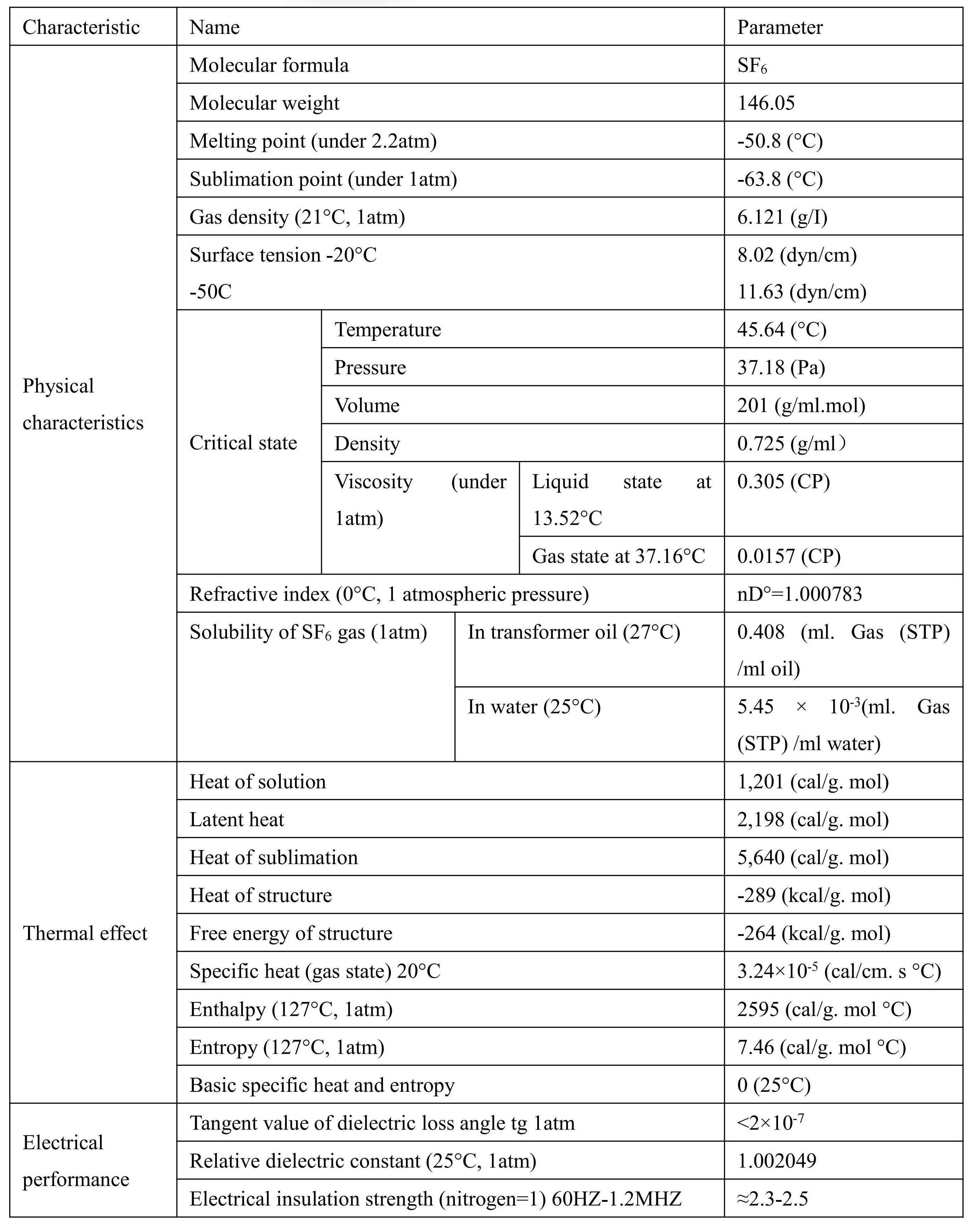
SF6 gas is a kind of excellent gas insulating material used for high-voltage electric power equipment, and is widely applied in the high-voltage breaker and other switchgear of the electric power industry; meanwhile, it is also used in the power distribution station of gas insulation, the gas insulation transmission line, etc. Some electrical performance and thermal properties of SF6 gas can make it meet the demand of electric system:
★High electric insulation strength
★Unique arc-extinguishing capacity
★Good heat conduction performance
★Excellent thermal stability
Beside these characteristics, SF6 gas has many psychical properties and chemical properties, and can make them become excellent electrical insulating materials of the electric power industry. The characteristics of SF6 gas are non-toxicity, non-flammability, inert gas and non-corrosiveness.
1.5.4.2 Component index
SF6 gas is manufactured by the most advanced automatic system and the most reliable new technologies, and is installed in steel cylinders for transportation in liquid and gas equilibrium mixture. The production can meet the following strict technical parameter requirements, and can also meet the provisions stipulated in No.376 standard issued by IEC. Form: colorless and transparent
Odor: colorless
Purity: 99.8% by weight (minimum value)
Humidity: 8PPm by weight (maximum value)
Content of carbon tetrafluoride: 0.05% by weight (minimum value)
Hydrolyzed fluoride: such as HF: 0.3PPm by weight (maximum value)
Air content such as N2: 0.05% by weight (maximum value)
Toxicity: non-toxic
1.5.4.3 Safety precautions
☆ As for the toxicity of SF6 gas, we have placed the laboratory rat inside the gas mixed with 80% SF6 gas and 20% oxygen and observed for 20 days. Through judging by appearance, there are no changes, and there are also no abnormalities after the dissection. However, it shall be noticed that, under the effect of high temperature and electric arc, SF6 gas will resolve slowly.
☆ The decomposers of SF6 gas contain low-sulfur sulfur fluoride, and after it is hydrolyzed, it will generate SO2 and HF. Although no virulent S2F10 has been found out in the electric arc and the decomposer under high temperature, when encountering with SF6 gas after arcing, please be careful, to avoid inhalation poisoning, because it might contain toxic decomposer.
☆ The decomposers of SF6 gas can be absorbed by the mixture of respectively 50% soda lime (NaOH + CaO) and activated aluminum oxide (especially the dried Al2O3). The quantity of absorbing agent shall be subject to 10% of SF6 gas quantity (by weight).
☆ In order to better protect the environment, please do not directly discharge SF6 gas into the atmosphere.
1.5.4.4 Transport and storage of SF6 gas cylinder
1) Do not put SF6 gas cylinder upside down, and be careful to carry it, because it is quite heavy (which is equivalent to 120Kg/bottle)
2) The storage of SF6 gas cylinder shall avoid the long-term exposure under sunlight.
1 Preparations before installation
5.1.1 Before the installation, it is requested to check the site environment: (this item can be confirmed by the salesman in advance after receiving the users’ installation notice)
5.1.2 The site terrace, trench and other environments shall be clean, with no sundries stacking on the ground or the aisle. In case of adopting indoor installation, the installation environment must be an enclosed environment isolated from the external environment.
5.1.3 In case of conducting pre-buried box iron for the site terrace, it shall be 10mm above the basic plane, and the horizontal error for the entire basic horizon shall not exceed 5mm, and the horizontal error for the box iron installation surface shall not exceed 3mm; whether the field installation of lifting appliances, tools, etc. is arranged in place.
5.2 Preparation work after the installation personnel enter the site
5.2.1 During field cleaning, it is requested to clean the terrace and trench.
5.2.2 As per the requirements stipulated in the foundation drawing and overall layout diagram of GIS equipment, use ink fountain (or marking pen, etc.) to draw each interval, distance and the central line between the main bus bar on the terrace for the installation of GIS equipment in place. 5.2.3 Outdoor installation shall be conducted in sunny and windless weather; in case that it is requested to conduct in windy weathers due to special conditions, please set temporary protective measures for GIS docking part, such as the protective shed, and avoid the installation in rainy days.
5.3 Product installation procedures
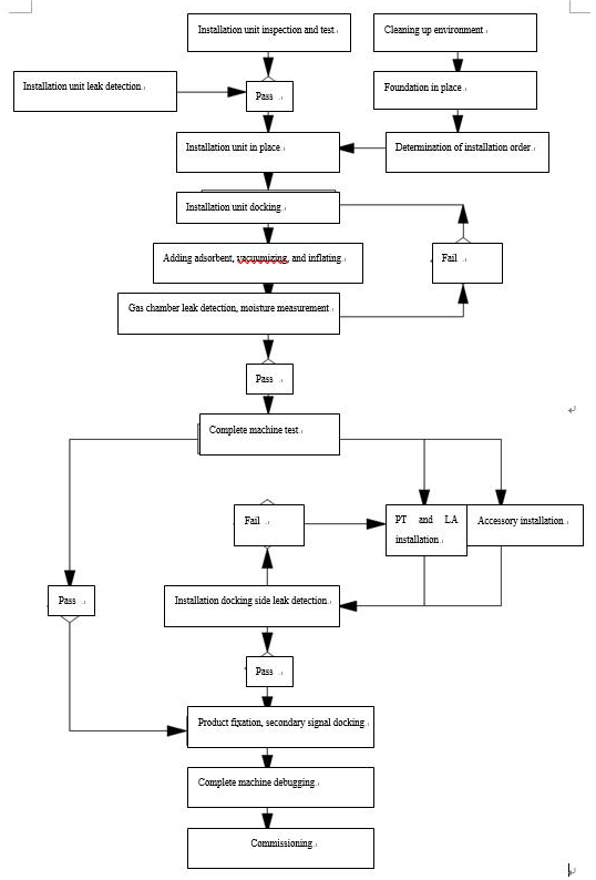
Before product installation, it is requested to confirm the installation sequence of each interval at the installation and operation manual of each station; after GIS is transported to the manufacturer, it is requested to install as per the plan and procedures formulated by each station.
5.4.1 Installation unit
a) Installation unit regards the packaging unit when products leave the factory as the basis;
b) Installation unit can be constituted by one gas chamber or several gas chambers;
c) The inspection of installation unit includes the following contents: CT test, the inspection of non-disassembly gas chamber, and the measurement of circuit resistance;
d) During the ex-factory of gas chamber that requires field disassembly, it shall be filled with 0.03MPa high-purity nitrogen, and gas chamber without the request of disassembly shall be filled with 0.03MPa SF6 gas.
5.4.2 After the first installation unit is put in place, it is requested to use electric welding and pot welding for fixation, do not cause welding failure.
5.4.3 Installation unit docking
a) Before docking, it is requested to clean the environment of the working part, and if necessary, spray some water on the ground to remove the dust generated during the movement of installation personnel;
b) Firstly, disassemble two packaging cover plates or end enclosures for docking, and be careful during the disassembly; do not bring out conductor or other parts, and before the disassembly, it is requested to implement degassing treatment for corresponding gas chambers.
c) When it is impossible to dock immediately, it is requested to use plastic film to wrap the docking port, and prevent the entrance of dust inside GIS;
d) When cleaning GIS docking surface, please be careful, and do not put tools or other sundries inside GIS;
e) When docking under humid environment, it is applicable to blow in high-purity nitrogen at the docking part, to decrease the moisture inside GIS during the docking;
f) During the docking, hoisting movement must be stable, to ensure that the barrel and conductor can be correctly docked, and if necessary, open the manual control cover of the docking part for inspection;
g) After the two docking surfaces are basically closed, install the bolt, evenly and symmetrically tighten the bolt and nut around the flange. When tightening, try to adopt torque spanner, and refer to Table 1 Tightening Torque Meter for the tightening torque. In case of finding that gas leakage at certain part of the sealing surface exceeds the stipulated value, it is allowed to exert the torque that is 20% higher than the tightening torque table on the connecting bolt within the region for fastening.
Overview
The ZHW-145 circuit breaker is the most important component of the ZHW-145 hybrid gas insulated switchgear (HGIS), mainly used to break short-circuit current and load current.
The ZHW□-145 circuit breaker adopts a three-phase common box structure, and the arc
extinguishing chamber adopts the self-energy arc extinguishing principle and is equipped with a
spring operating mechanism.
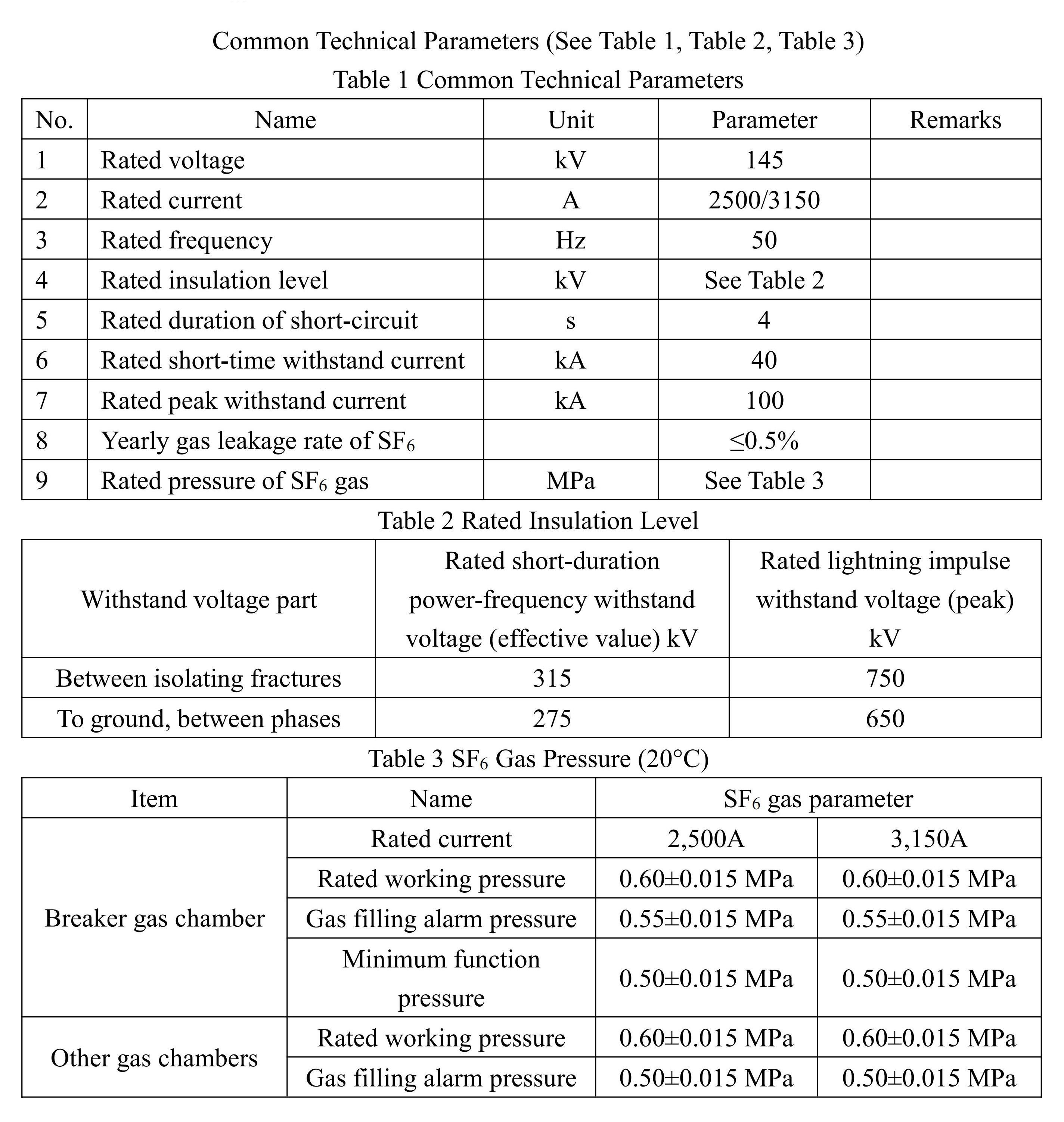
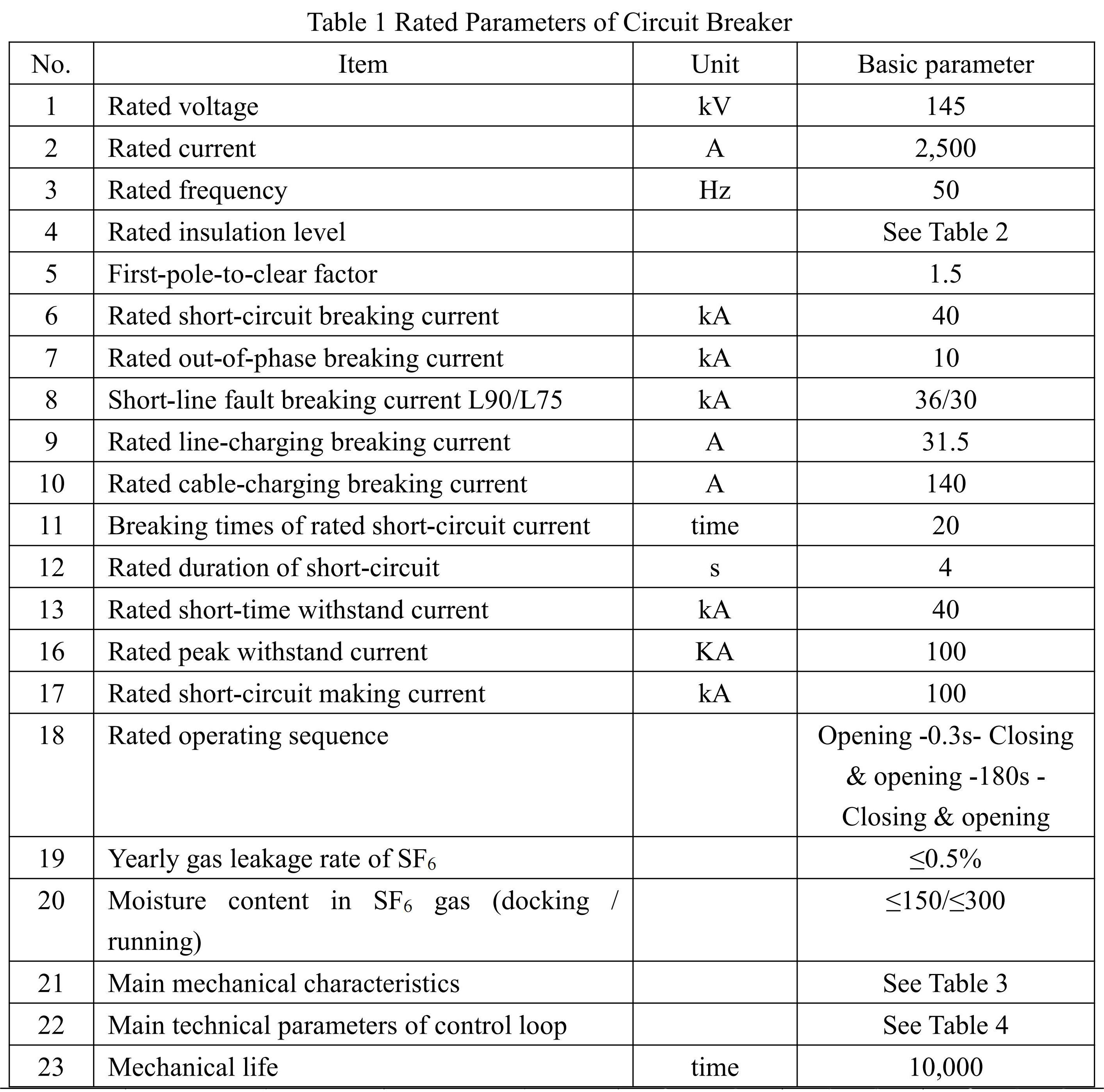
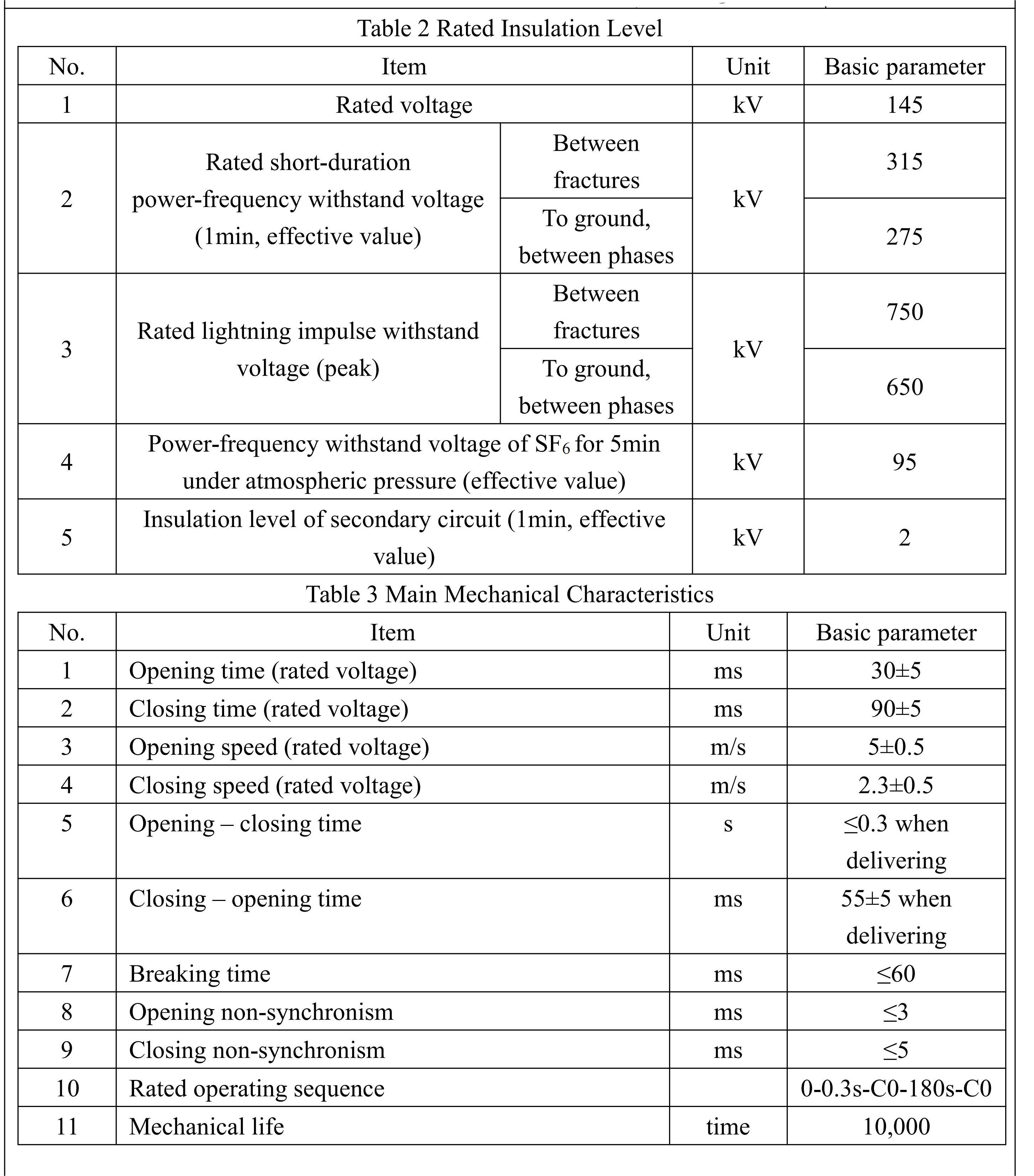
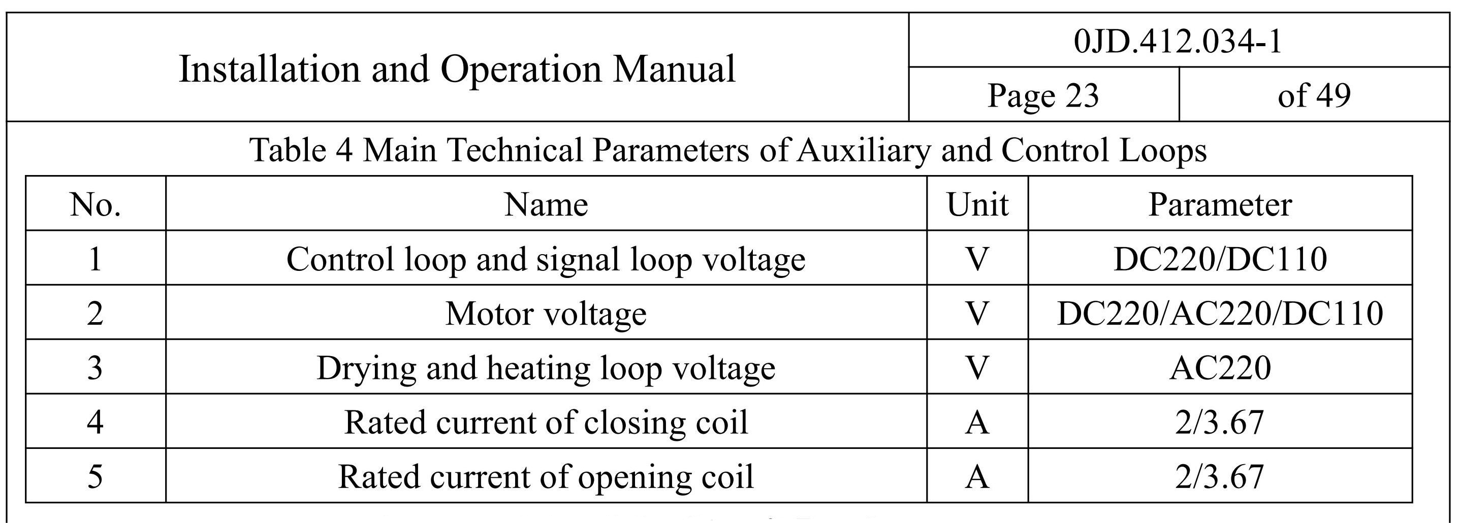
Technical Parameters
See Table 1 for rated technical parameters of circuit breaker and operating mechanism.
Structure and Operating Principle of the Circuit Breaker
The structure and boundary dimensions of the single-pole circuit breaker assembly are shown in Figure 1. The circuit breaker unit consists of three major parts including a single arc extinguishing chamber, a shell and a spring operating mechanism in the lower part of the arc extinguishing chamber, and the arc extinguishing chamber is the core of the circuit breaker and can realize the conduction and breaking of the circuit.
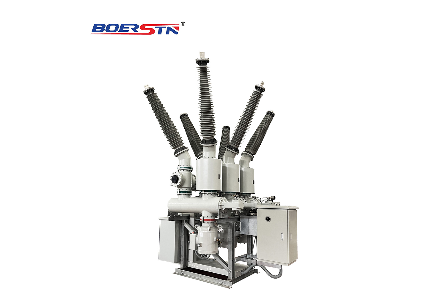
There are two arrangements for the circuit breaker's outgoing line. One is that the circuit breaker's incoming and outgoing lines are on both sides of the circuit breaker, called the Z-type outgoing line arrangement, and the other is that the circuit breaker's incoming and outgoing lines are on the same side of the circuit breaker, called U-shaped outgoing line arrangement. The specific use . should be determined according to the wiring method and layout area of each substation in the overall layout design. (U-shaped outgoing line arrangement is shown in Figure 1).
The total height of the circuit breaker is 1,950mm and the width is 550mm.
3.2 Structure and operating principle of the arc extinguishing chamber
3.2.1 Structure of the arc extinguishing chamber The structure of the arc extinguishing chamber is shown in Figure 2. The moving and static contacts are connected and insulated by the insulating cylinder. The static contact assembly is located at the upper part of the arc extinguishing chamber, consisting of the static arc contact, static contact base, main contact and the guide cylinder, etc.; the moving contact assembly is located at the lower part of the arc extinguishing chamber, consisting of the air cylinder, moving
arc contact, moving contact, pull rod, large nozzle, small nozzle, moving contact base and the support cylinder and other spare parts; the entire arc extinguishing chamber is fixed and connected by the insulating stand and the circuit breaker cylindrical shell, and the moving part is connected by the insulating pull rod through the inner connecting lever and the connecting lever box and the spring operating mechanism mounted at the lower portion to ensure the mechanical characteristics and the operating function of the entire motion system.
Feedback form contact with us
Related Product
LW36-72.5~252KV Outdoor SF6 Circuit Breaker
Summary
LW Series self-energy SF6 Circuit Breaker is a three-pole/single-pole AC 50Hz/60Hz outdoor high voltage power transmission...
LW30-72.5~252KV Outdoor SF6 Dead Tank Circuit Breaker
Dead tank type
SF6 Gas Circuit- Breaker
72.5kV up to 252KV, 25kA~63kA, 1250A~4000A for Outdoor
Three phase/Si...
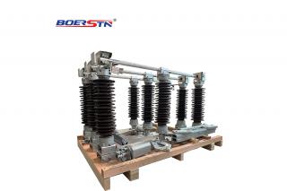
40.5~252KV GW7 Outdoor High Voltage Disconnector Switch
1.Application
GW7-145D(W)series is a kind of three column ,horizontal/vertical,double break out-door three phases AC HV disconnect...
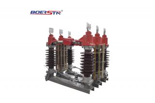
40.5~145KV GW4 Outdoor High Voltage Disconnector Switch
Ambient Condition:
• Altitude:≤1000-3000m
•Ambient temperature:no more than 40°C and no less than -30°C(no less than -40°C ...