40.5~252KV GW7 Outdoor High Voltage Disconnector Switch
GW7 Type serial High Voltage Outdoor Disconnector comply with requirements in IEC62271-102:2002《AC Disconnecting Switches and Earthing Switches》and IEC60694:1996 《Common Clause for High voltage Switchgear and Control Devices》.
Share This Product:
  • SWITCHGEAR STRUCTURE
  • SWITCHGEAR INSTALLATION
  • SWITCHGEAR INSTALLATION
  • SWITCHGEAR INSTALLATION

1.Application

  • GW7-145D(W)series is a kind of three column ,horizontal/vertical,double break out-door three phases AC HV disconnector (briefed as GW7-145 type disconnector), and applicable for the electric system with rated frequency 50/60Hz ,rated voltage 145for the HV power line switching when they are free of loads,and to electric isolate or connect the being repaired HV busbar、CB etc HV electrical apparatus from the live HV lines.Meanwhile,when the operating mode in the power system is nessary to change , it is also applied to breaking and making busbar for transferring current as well as the charging current of specified range for PT,lightning arrestro,etc under the condition of not disconnecting or breaking and making load current.

2.Product specification and type (illustration)

3.Applicable standards

  • 1. IEC62271-102High voltage AC Disconnector and Earthing Switch

  • 2. GB/T 11022-2011 Common specification For High-Voltage Switchgear and Controlgear Standard

  • 3. DL/T 486-2010 Technical Conditions For Order of High Voltage AC Disconnector and Earthing Switch.

  • 4. DL/T 593-2006 High Voltage AC Disconnector and Earthing Switches .

4. Operating Environment

  • 1. Ambient temperature:-50℃~+50℃;

  • 2. Altitude: no more than 2000m(if it is more than 2000m, the product adaptability can be improved based on GB standard);

  • 3. Wind pressure: no more than 700Pa(equivalent to a wind speed of 34m/s);

  • 4. Seismic intensity: no more than 9 degrees;

  • 5. Ice coating thickness: no more than10mms;

  • 6. Environment-pollution class: class Ⅲ and Ⅳ;

  • 7. Installation site should be free of combustible, explosive hazard and chemical corrosion as well as violent movement;

  • 8. Special operating conditions should be resolved through consulations by users and manufacturer;

5. Characteristic

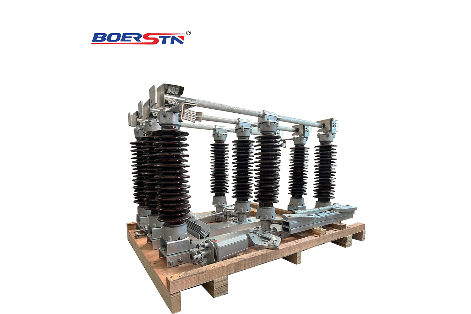
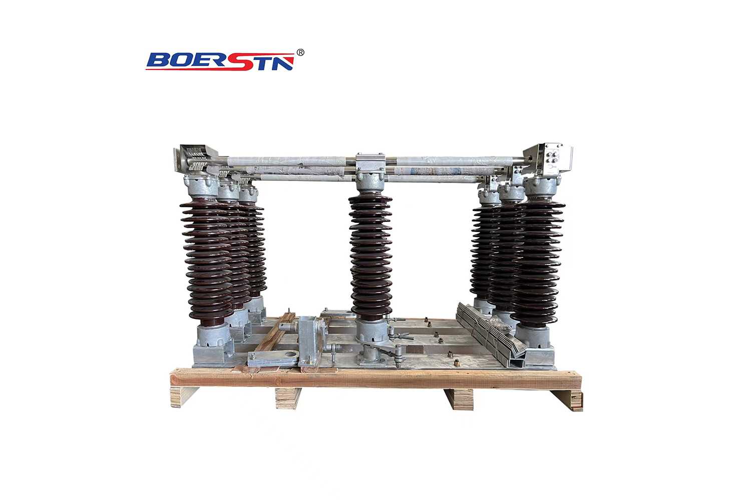
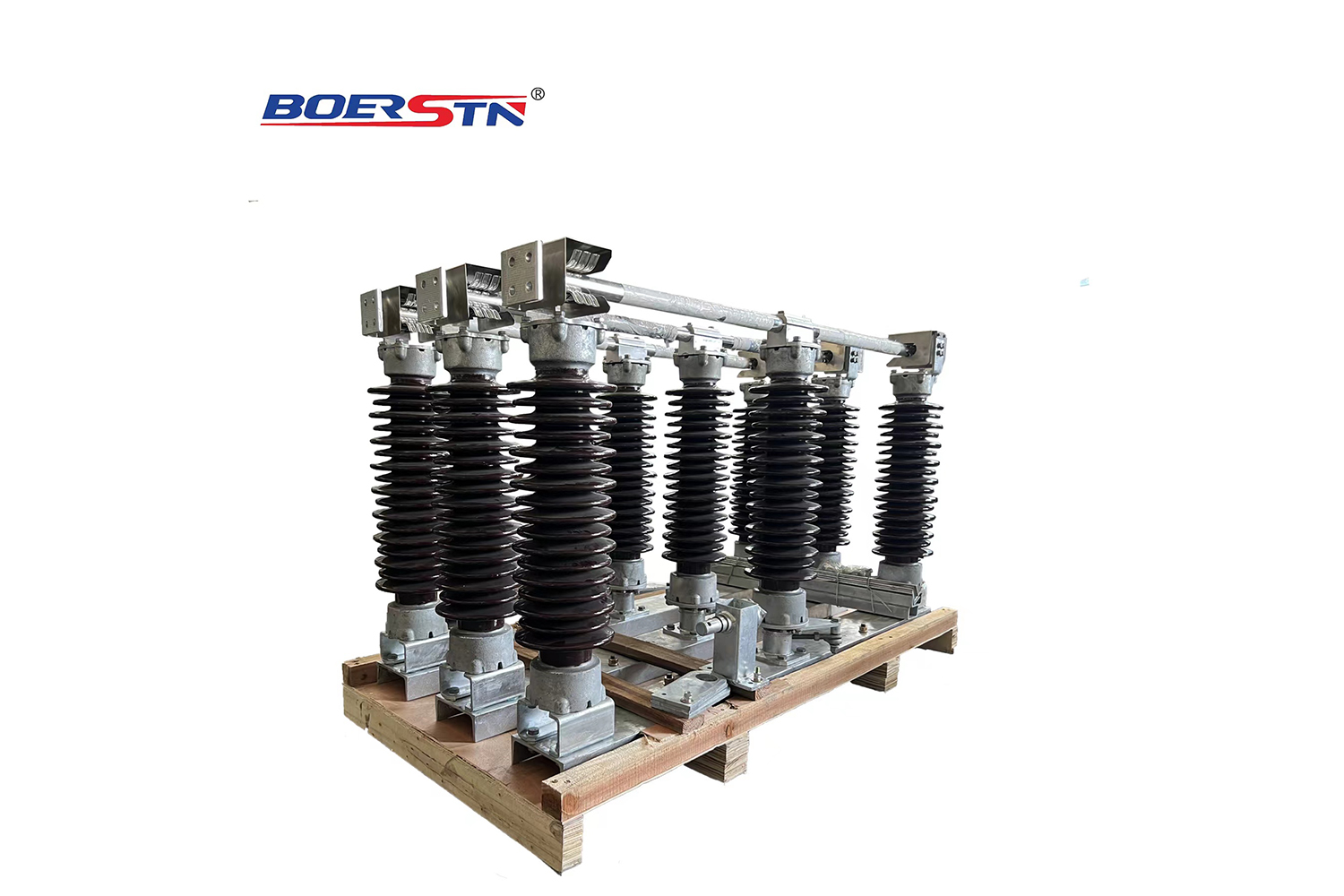
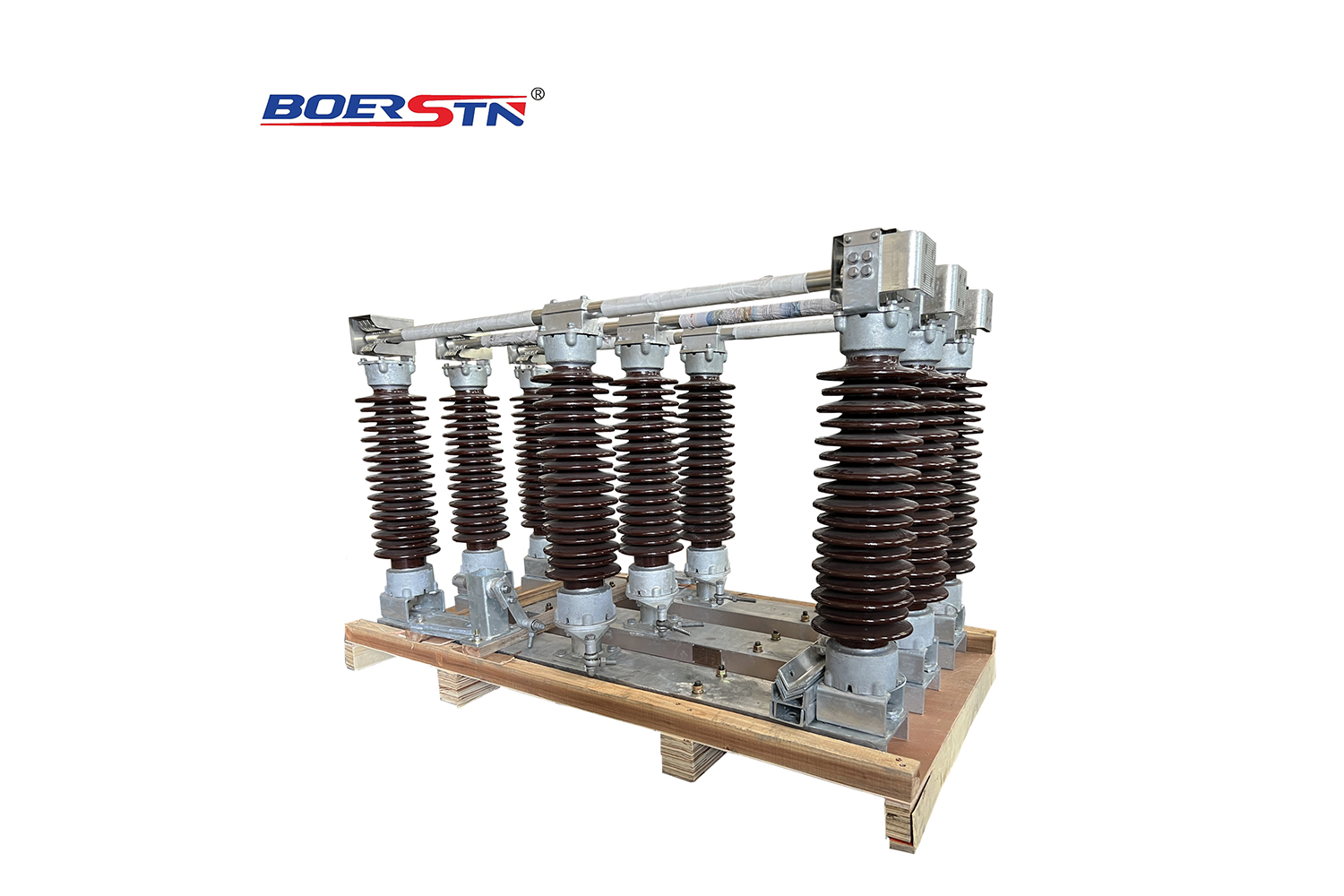
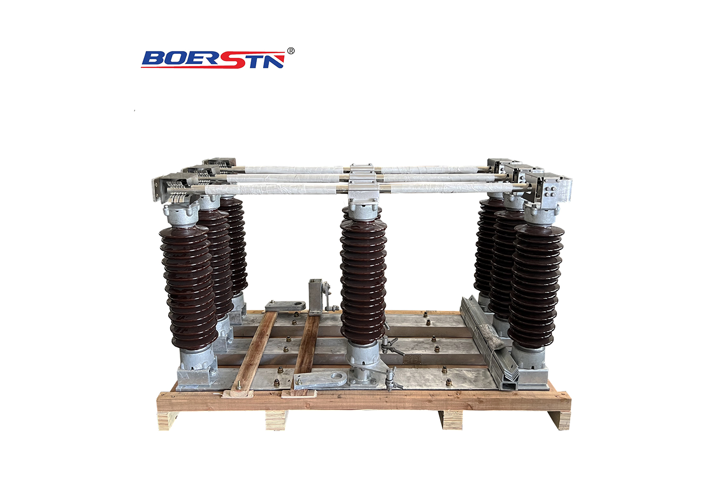
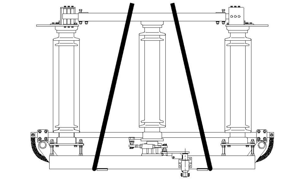
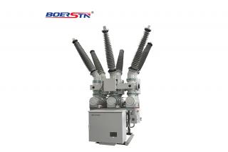
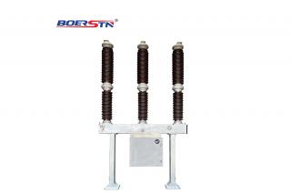
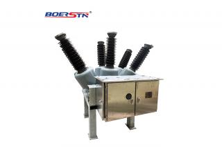
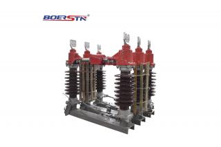
  • GW7-145 disconnector is a new kind of disconnector developed and manufactured by our company and based on GW7-145 technology. This disconnector is specially to solve the problem like porcelain broken , incorrect operation ,parts damage and deform ,over heat in conducting circuit,corrosion etc,to improve quality and reliability. This kind of product the design reasonable,excellent performance and has the following characteristics:

  • a. The conducting rod adopt the angle aluminum structure, increasing conductive cooling area ,improving conductivity reliability.

  • b.Adopt new type contacts and external pressure type contact finger structure, compare with the primary structure, the surface area of contacts and contact finger larger than before and have a good heat dissipation capability,avoid the influence of skin effect, and have better self-clean and stand wear and tear ability meanwhile. The depth of this structure of contact inserted contact finger deeper than before so that improve the conductivity reliability.

  • c.Adopt the advanced silvering technology graphite plated silver to ensure the thickness and hardness of silver coating, greatly improve the adhesive force of cladding. It is also applied appropriate contacts pressure to ensure the silver coating not fall off for long term operation.The technology of graphite plated silver improve the life of silvering parts,the silvering contact surface can work over 10000 times.

  • d.The twist link adopt the oil free self-lubricating bearing and insulating oil free bearing. The transmission link adopt hot galvanizing link bearing. The material of the all dowel adopt aluminium bronze or stainless steel and have strong anticorrosion capability , low twisting resistance, small fit clearance,transmission reliable, avoid the corrosion of spindl and ensure twist flexible.

  • e.Adopt high quality raw material or high anticorrosion surface to improve the anticorrosion capability. For example , all the surface of steel parts adopt hot galvanizing technology or stainless steel material, the material of the all dowel adopt aluminium bronze or stainless steel ,the non-conductive contact surface of contact tube adopt anodic pxidation treatment.

  • f.The earthing switch adopt single-step structure, the earthing moved contacts adopt self-reliance structure.The structure simple and beautiful,small operating force, action reliable.

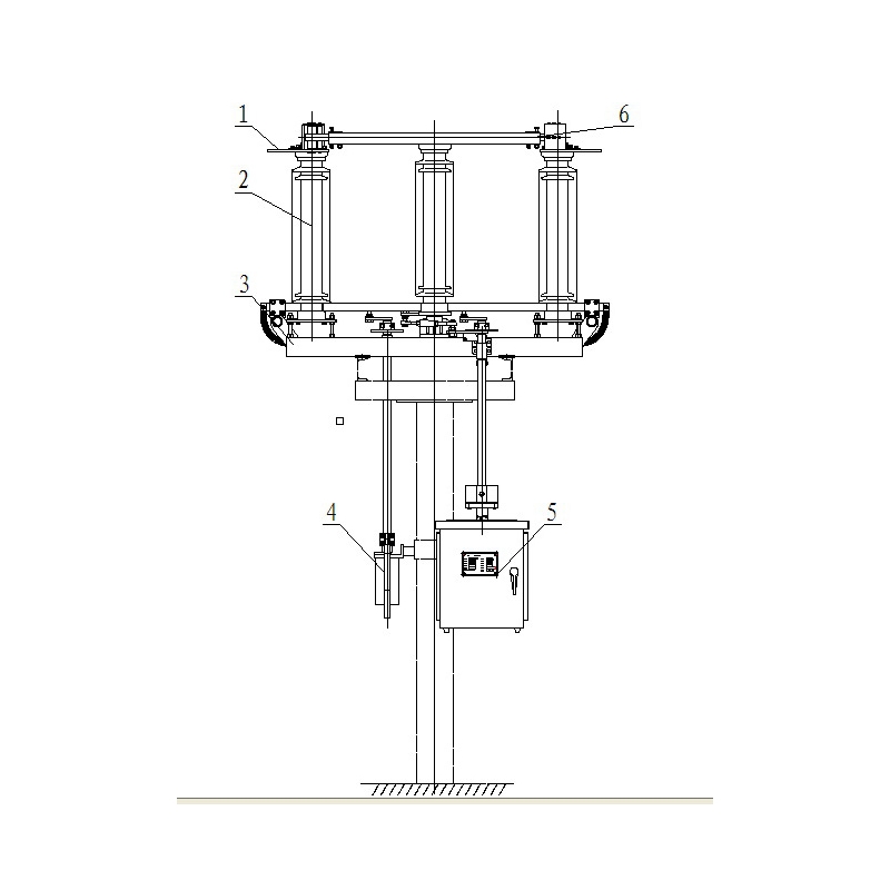
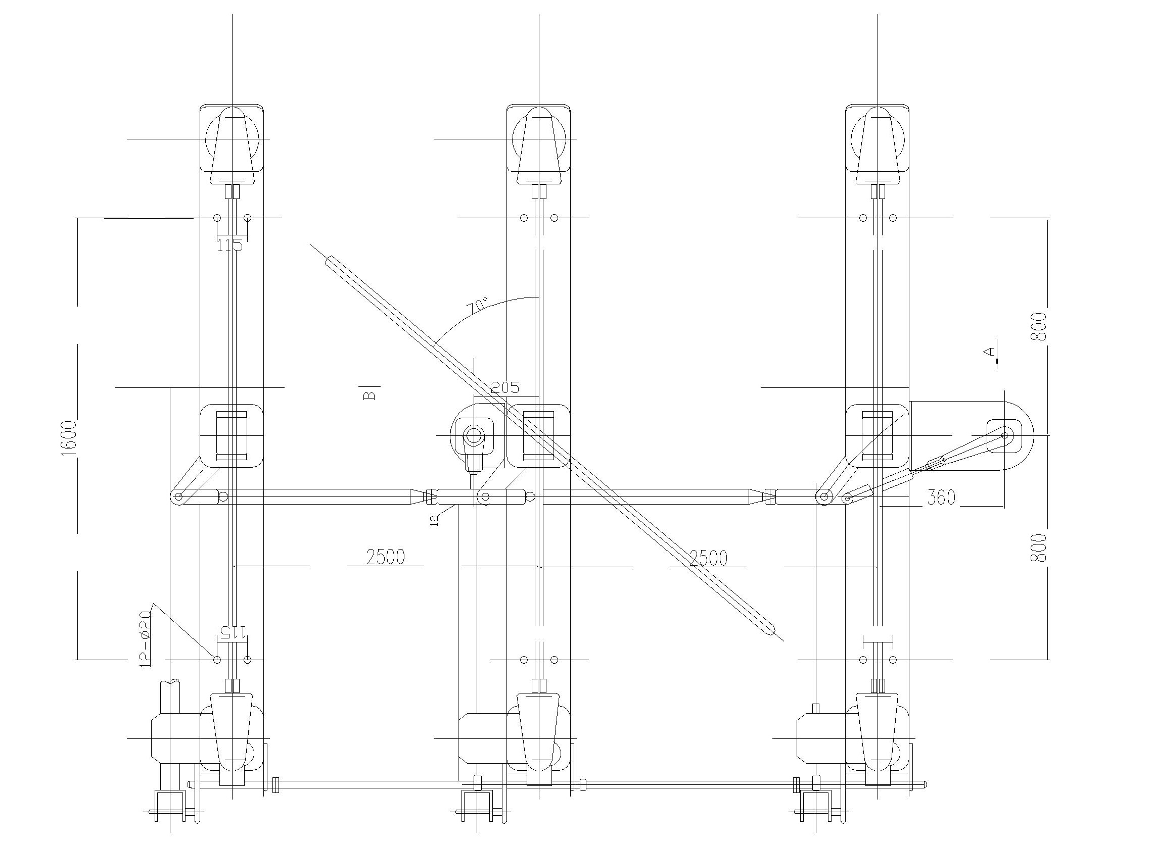
  • g.The connect way of vertical connecting rod which connect the mechanism of disconnector and earthing switch and noumenon and the level connecting rod which connect three phase change from on-site welded to plywood and hoop.The level connecting rod which connect main blade three phases adopt positive and negative wire connection and all can realize the infinitely variable control. Cancelling the way of welded and drilling is convenient for client to install,debugging,disassembly and maintain. It also avoid the corrosion caused by welded.

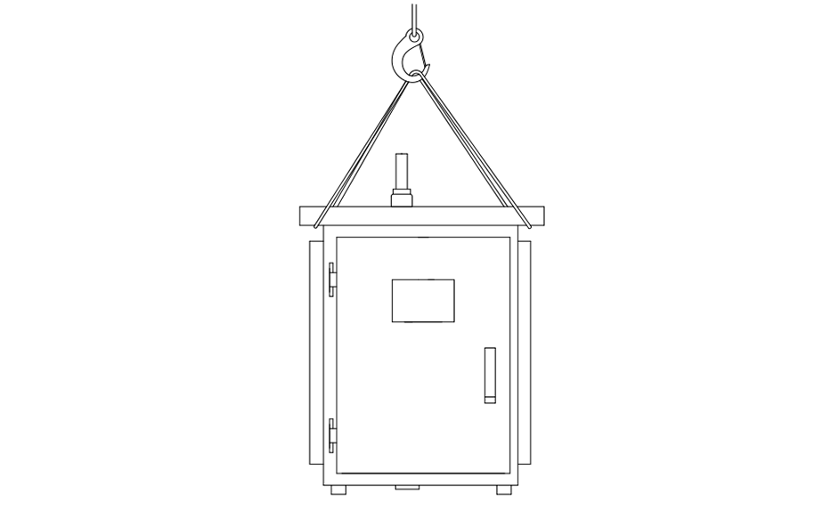
  • h.The motor operation mechanism box adopt stainless steel welded,the manual operation box adopt aluminium alloy material, the shape beautiful , good entirely leakproof capability. The motor operation reducing gearbox purchase famous joint stock brand, good leakproof capability , smooth operation without noise. Adopt foreign famous brand component,operation reliable , locking function completed.

  • i.Adopt the stable performance ,quality reliable post insulators and request the sintering position of porcelain exposed sand and adopt the waterproof construction so that satisfy the safety factor under 2.5 times mechanical load. Strictly select the porcelain manufacturers and take the acceptance test to ensure that the porcelain high quality and reliable.

  • j.The parts above the ground can be supplied overall according to the request and provide the galvanized steel structure and vertical ,horizontal driving rod.

Classification and technical parameter

  • 1. Product classification

  • 1. Classification according to the current:1250A,2000A.

  • 3. Classification according to the number and position of earthing switch: no earthing ,left earthing, right earthing ,double earthing.

1. The mainly technical parameter of products in table 1

NO.

Item

Unit

Technical parameter

1

Rated voltage

kV

145

2

Rated current

A

1250

2000

3

Disconnector

Rated peak withstand current

kA

100

Rated short time withstand current and duration

kA

40/4

4

Earthing switch

Rated peak withstand current

kA

100

Rated short time withstand current and duration

kA

40/4

5

Rated(1min) power frequency withstand voltage
(effective value)

To earth

kV

275

Across isolating point

315

6

Rated lighting impulse withstand voltage
(peak value)

To earth

kV

650

Across isolating point

750

7

Switching busbar induced current capability(busbar transfer voltage 100V)

A

400V、2500A、100 times

8

Switching micro capacitive current

A

2

9

Switching micro inductive current

A

1

10

Radio interference level

μV

≤500

11

Mechanical life

Times

10000

12

Rated terminal static mechanical load

Longitudinal level

N

750

Horizontal Level

1000

Vertical force

750

1. Parameter of structure shown in table 2


No.

Technical requirements

parameter

1

Insulating distance across the open contact (≥mm)

650

2

Insulating distance to earth (≥mm)

650

3

Main circuit resistance (≤μΩ)

80

4

Three-pole of main blade closing asynchronism(≤mm)

8

5

Three-pole of earthing blade closing asynchronism (≤mm)

8

6

Main blade O-C time incorporating with motor mechanism(s)

6±1

7

Main blade output rotation angle incorporating with motor mechanism

135°

8

Earthing blade output rotation angle incorporating with manual mechanism

90°

Product structure and operation principle

  • 1.The structure of disconnector

  • GW7-145 belongs to three-pole horizontally-rotated type disconnector, mainly including base, post insulators, movable contact head and static contact head for main blade, operating mechanism and etc. The earthing switch can also be mounted according to requirements. The base is made of process C type steel, middle of which is mounted with rotating bearing pedestal while others of which are made from the hot-dip zincing steel components/parts. The height of post insulators at both ends can be adjusted by moving the bolts at both ends of the base up and down. The side can be mounted with earthing blade, and on the base of the middle phase is mounted with transmission linkage and interlocking device for main/earthing blades.

  • Disconnector of each pole contains three insulator posts, each of which is made by stacking two sections of high-strength solid bar-shaped insulators(Fig.2.2). he insulation post plays such roles as conductive system insulation to earth and ensuring the mechanical stability for disconnector under dynamic and static loads. The lower ends of the post insulators at both ends are directly fixed on the base while their upper ends fixed with the static contact head. And the lower end of the post insulators in the middle phase is fixed on the bearing pedestal while its upper end fixed with the conductive blade.

  • The main conductive system consists of the static contact head and movable contact headof the main blade. The static contacts of the main blade consists of static contact base, contact finger, contact finger spring, closing location limit and hook plate, etc. The movable contacts of the main blade consists of movable contact plate, conductive tube and the rotary device inside the driving gearbox, etc.

2.Interlocking of disconnector and earthing switch

  • The mechanical interlock between the earthing switch and the disconnector is realized through the interlocking plate mounted on the rotating shaft of the main blade and earthing blade of the base in the middle phase. And the interlock device enjoys sufficient mechanical strength. When the disconnector is in the closed position, the interlocking plate in the base makes the earthing switch unable to close. In contrast, when the earthing switch is in the closed position, the interlocking plate may also be applied to preventing the disconnector from closing.

3.Motor operating mechanism

  • CJ6-G belongs to the outdoor power-type mechanism, type CJ6-G motor-driven operating mechanism is driven by three-phase AC motor and is through gear and worm wheel/worm decelerating device to transmit the torque to the mechanism output shaft. The mechanism is equipped with auxiliary switch and hand-operated opening/closing device, and such components as heater, temperature/humidity controller, phase-order protector, lighting lamp and manual interlocking switch can also be equipped so as to facilitate the use for users.

4.Manual operating mechanism

  • Type CS14-G hand-operated operating mechanism is equipped with hand-operated handle, and is through the worm wheel/worm decelerating device to transmit the torque to the mechanism output shaft.The mechanism is equipped with auxiliary switch and padlock hole as well as the electromagnetic lock can also be attached based on users’ requirements.

5.Disconnector operation principle

  • When the disconnector is closed, CJ6-G motor-driven operating mechanism through the drive connector and vertical linkage drives the drive rotating shaft mounted in the base of the main operating pole to rotate about 135°,and then by means of the four-linkage made up of crankarm and linkage to drive the bearing pedestal and bring along the middle post insulator to rotate about 70° so as to make the the movable contacts contact with static contacts and complete the closing operation. The opening operation is the opposite of the above.The drive crankarm on the master pole connects the drive crankarm of two slave poles through the interphase horizontal linkage, enabling the three-pole disconnector to complete opening/closing operation in a synchronized manner.

6.Earthing switch operation principle

  • Type CS14-G hand-operated operating mechanism is through the vertical and base rotating shafts as well as the spatial four-linkage of the earthing blade to drive the crossarm rotating shaft on the base to rotate 90° and bring along the earthing blade to rotate 90° in the vertical plane. After that, the earthing static contact head goes into the gap of contact finger of the earthing blade so as to deform the aluminum plates in an elastic manner at both sides of the earthing blade and clamp the earthing static contact head. The opening operation is the opposite of the above. The earthing blade rotates 90° in the vertical plane, withdraw the earthing static contact head and return to the horizontal opening position, and then a clear vertical break formed by the earthing blade and the earthing static contact head above it can be seen. Due to the principle of torque balance on both ends of the rod, the movable arm of earthing blade boasts low operating force, smooth movement and reliable closing.Two slave poles enable the three-pole to operate in a synchronized manner by connecting the drive crankarm and linkage with the drive crankarm on the master pole.

Unloading and hoisting

  • 1. Attention should be paid not to damage the equipment when loading/unloading and hoisting the packing boxes.

  • 2. Bind materials through proper ways as shown in Fig.1 and hoist in a smooth and stable manner.

Package and delivery

Typical delivery unit

  • 1. The disconnector parts are overall packed based on set unit

  • 2. The main blade tubeand accessories are packed based on contract unit .

  • 3 .Operating mechanism is individual packed.

  • 4. The vertical,horizontaltransfer bay are packed based on contract unit.

Packaging type

  • 1. Steel frame and bare package are applied to the conductive system, base part and drive linkage. The air-cushion diaphragm is applied to packing the easily-damaged surfaces;

  • 2. All the delivery units such as mounting accessories, static contact head of the main blade and operating mechanism packed in boxes adopt crates for package, and careful loading and unloading should be carried out accordingly based on the symbols or markings at the side of the boxes;

  • 3. The shipping package design ensures a complete protection for the possible mechanical damages occurred in the process of shipping and loading/unloading as well as for weather change so as not to damage the equipment. And the quality characteristics tested in various working procedures of all production processes maintain unchanged.

Unloading and hoisting

  • 1. Attention should be paid not to damage the equipment when loading/unloading and hoisting the packing boxes.

  • 2. Bind materials through proper ways as shown in Fig.1 and hoist in a smooth and stable manner.

Fig.1A Hoisting method of single phase GW7-145 Fig.1B Hoisting method of motor mechanism

Fig.1 Hoisting picture


  • Please open the packing boxes before installation at a place where is close to the installation site. Place various units based on unit and avoid missing on site, as well as ensure that the hoisting equipment can conveniently hoist them.

  • IX.Installation and commissioning

  • ※Note:Due to that this disconnector has different mounting/arrangement methods regarding foundation height and interphase distance on site, in order to better understand that, please check the Mounting Diagram provided by our Company specifically for your order when referring to the Mounting Diagram in this manual.


1、Preliminary preparations before installation

  • 1. Read this manual carefully before installation. For installing this disconnector correctly, the connection dimensions for foundation and steel bracket must adhere to the Mounting Diagram (Fig. 4, Fig. 5,) in this manual or the Mounting Diagram provided by our Company specifically for your order.。

  • 2. Read the instruction manual of the motor-driven operating mechanism(if required) and check whether the voltage of power source is consistent

  • Process the contact surfaces of permanent live components(it is not necessary to process the assembled components when they leave factory) due to that current will flow through those surfaces(i.e. terminals).Processing methods are listed below:

  • 1. Use stainless steel wire brush or fine sandpaper to eradicate the oxide, and then use the absolute ethyl alcohol or acetone to get rid of the grease traces of the foresaid surfaces, immediately coat with conductive grease. After that, connect the two surfaces as soon as possible.

  • 2. A thin layer of conductive grease must be coated with those surfaces flowing through instantaneous impulse current(i.e. surfaces of contact heads and contact fingers).

Installation and commissioning of single-pole disconnector

  • Base installation:

  • According to the requirements on site, following that the mounting locations of main and earthing blade mechanisms, hoisting base as well as the foundation bracket are aligned, use relevant standard parts to connect, and then measure the distance of both ends in the base between phases A and B, which is equal, and measure the distance of both ends in the base between phases B and C, which is equal. After that, fasten all the connection standard parts.

  • Adjust the locations of the nuts(Fig.4.1) on the adjustable bolts at both sides of the base. Apply the level in two orthogonal directions to ensuring that the square plate(Fig.4.2) for mounting the post insulators is horizontal and the distance between the top surface of the square plate and top surface of the base rectangular tube is 77mm. after that, fasten all the bolts on the adjustable bolt.

  • ※Note: When the movable contact head of the main blade and post insulator are hoisted together, never fasten the lifting rope at any position on the main blade and never fasten the lifting rope in the place where the insulator flange is cast. However, the lifting rope should be hung between the umbrella skirts in the upper section of the post insulator.

  • Installation of operating mechanism:

  • The operating mechanism(also called control box) includes the motor-driven operating mechanism for disconnector and the hand-operated operating mechanism for earthing blade, which are connected with vertical transmission rod through clamping component or flange respectively. Hoist the operating mechanism to the location indicated in the Mounting Diagram as and connect it to the foundation bracket. Do not screw up the fastening bolts beforehand.

  • Confirm that the drive crankarms of main and earthing blades as well as the operating mechanism are all in the opened position.

  • Installation of motor-driven operating mechanism::

  • According to the length and application of vertical linkage indicated in the Delivery List, select appropriate vertical linkage, insert both ends of the vertical linkage to the clamping component of the drive crankarm of main blade and the connection joint of motor-driven mechanism. Apply level in two vertical planes to confirming that the drive rotating shaft of the main blade are aligned with the rotating shaft of the operating mechanism. After that, fasten the operating mechanism to the foundation bracket and then fasten the clamping component to tighten the vertical linkage。

  • Installation of motor-driven operating mechanism::

  • Ccording to the length and application of vertical linkage indicated in the Delivery List, select appropriate vertical linkage, tighten the end with flange regarding vertical linkage with the flange on the rotating shaft of the hand-operated mechanism, and insert the other end to the clamping component of the drive crankarm of the earthing blade.Apply level in two vertical planes to confirming that the drive rotating shaft of the earthing blade are aligned with the rotating shaft of the operating mechanism. After that, fasten the operating mechanism to the foundation bracket and then fasten the clamping component to tighten the vertical linkage.

  • ※Note: Due to possible errors for such heights as foundation bracket and mechanism mounting on site, margin is reserved for the length of the vertical linkage provided by our Company. If the linkage is cut short for use on site, it is recommended that an anti-corrosion treatment should be applied to the kerfs.

Commissioning for three-pole disconnector

  • Commissioning for three-pole of the main blade regarding disconnector Confirm that the motor-driven operating mechanism of the main blade, drive crankarm of main blade on the middle-phase base as well as the main blade are all in the opened position, and then manually open and close the middle phase. When the mechanism reaches the opened and closed positions, ensure that the main blade at the same time reaches the opened and closed positions. Otherwise, loosen the connector on the main shaft of the mechanism and bolts of the clamping plate, slightly change the relative location of the vertical transmission rod and main shaft of the mechanism for a fine-tuning.One manual operation enables the disconnector to close, and observe the movement of the main blade. Apply connector and interphase horizontal linkage of main blade welded with bolts to connect the three-pole drive crankarm together, thus realizing three-phase synchronized operation, with non-synchronization for three-phase closing no more than 20mm. The non-synchronization can meet requirements through adjusting the length of the interphase horizontal linkage.

  • Commissioning for three-pole of the earthing blade regarding disconnector:

  • Check that the hand-operated operating mechanism of the earthing blade, earthing blade and three-pole drive crankarm of earthing blade are all in the opened position, and then manually operate the earthing blade, observe whether the closed position of the earthing blade is vertical. If it is not vertical, adjust the length of the adjusting linkage of the earthing blade to change the rotating angle of the earthing blade.

  • Make the three-pole earthing switches are all in the closed position, mount the horizontal drive connectors of middle and side phases respectively on the three-pole drive crankarm of middle and side phases, and then connect and fasten the horizontal drive connectors of middle and side phases through the three-pole horizontal drive rod of the main blade.

  • Manually open and close the three phases. When the mechanism reaches the opened and closed positions, check whether the three-phase main blade is simultaneously closed in place and whether the closing synchronization meets the requirements in Table 2. If it fails to meet the requirements, loosen the retaining nut of the stub bolt connecting the horizontal drive rod and horizontal drive connector of the middle phase, and then fine-tune the length of the stud bolt.

  • Mechanical interlocking adjustment

  • It is required that the circular plate on the bearing pedestal and connection rotating shaft of the main blade mechanism should be moved into the crescent of the interlocking plate when the disconnector is in the closed position, at this time the earthing switch can not be closed. On the contrary, when the earthing switch is in the closed position, the outer rim of the interlocking plate should be moved into the crescent of the circular plate on the bearing pedestal and connection rotating shaft of the main blade mechanism, enabling the disconnector fail to close. The interlocking can be accomplished by adjusting the length of rods

  • ※Note: A number of times of manual opening and closing must be applied to the disconnector and earthing switch. Only after everything is normal, can the motor-driven operation be applied. X.Final Inspection and Fine-tuning before Check & Acceptance at mounting site

  • According to the length and application of vertical linkage indicated in the Delivery List, select appropriate vertical linkage, insert both ends of the vertical linkage to the clamping component of the drive crankarm of main blade and the connection joint of motor-driven mechanism. Apply level in two vertical planes to confirming that the drive rotating shaft of the main blade are aligned with the rotating shaft of the operating mechanism. After that, fasten the operating mechanism to the foundation bracket and then fasten the clamping component to tighten the vertical linkage。

  • Installation of motor-driven operating mechanism::

  • Ccording to the length and application of vertical linkage indicated in the Delivery List, select appropriate vertical linkage, tighten the end with flange regarding vertical linkage with the flange on the rotating shaft of the hand-operated mechanism, and insert the other end to the clamping component of the drive crankarm of the earthing blade.Apply level in two vertical planes to confirming that the drive rotating shaft of the earthing blade are aligned with the rotating shaft of the operating mechanism. After that, fasten the operating mechanism to the foundation bracket and then fasten the clamping component to tighten the vertical linkage.

  • ※Note: Due to possible errors for such heights as foundation bracket and mechanism mounting on site, margin is reserved for the length of the vertical linkage provided by our Company. If the linkage is cut short for use on site, it is recommended that an anti-corrosion treatment should be applied to the kerfs.

X.Final Inspection and Fine-tuning before Check & Acceptance at mounting site

  • 1. Check dimensions and verify the correctness of connection for various transmission rods and connecting bolts based on the Mounting Diagram.

  • 2. Manually and respectively manipulate the disconnector and the earthing switch for 3~5 times to check whether the operation is smooth, contact is good and the opening/closing position is correct.

  • 3. Check whether all the relative movement parts as driving and rotational parts are lubricated, as well as whether all the axle pins and bolts are securely fastened.

  • 4. Check whether the disconnector and the earthing switch are securely interlocked.。

  • 5. Manually operate the motor-driven operating mechanism. When the main blade of the disconnector is in the closed position, the movable and static contact heads have a reliable contact, and the movable contact plate should be in the vertical state. The three-pole closing non-synchronization measurements for the main blade are no more than 5mm while three-pole closing non-synchronization measurements for the earthing blade are no more than10mm。

  • 6. The main circuit resistance measurements should meet the values in Table 2(measuring location is from the left terminals to the right ones).

  • 7. Check whether there is oil dripping from the permanently-sealed reduction gearbox onto the bottom of the operating mechanism box.

  • 8. When fully opened or fully closed, the position indicator mounted on the operating mechanism indicates correctly.

  • 9. Check the auxiliary contacts of the operating mechanism for the main and earthing blades switch normally as well as the output position signal is correct(when it is in the closed position, such contacts of auxiliary switch as 1-3, 5-7 and 9-11 are the normally-open ones while such contacts as 2-4, 6-8 and 10-12 are the normally-closed ones).

  • 10. Check the lighting, heater and remote/local change-over switch regarding motor-driven operating mechanism as well as manually-operated blocking switch are working properly, apply a power-frequency withstand voltage of 2000V to the secondary circuits for 1min and no breakdown against ground is found.

  • 11. When the power source is energized, the opening and closing shall be normal in the following conditions: manipulate 5 times under a rated voltage of the motor, as well as respectively manipulate 3 times under an 85% and 110% rated voltage of the motor. And the movable and static contact heads are in a good contact state and no abnormality occurs.

  • 12. Check whether the operation of electromagnetic lock is normal.

  • 13.Turn the main and earthing blades to the opened position and standby mode.

XI.Documents attached

  • 1. Product certificate of conformity

  • 2. Installation and usage instruction manual

  • 3. Delivery List

  • 4. Instruction manual of motor-driven operating mechanism(if required)

  • 5. Packing list

XII.Ordering Notice

  • 1. Type, specification and quantity;

  • 2. Rated voltage and rated current; The motor voltage and the control coil voltage as well as the pair number of the auxiliary contact(if no indication, it will be 10 normally-open contacts and 10 normally-closed contacts) of the CJ6-G motor-driven operating mechanism that is used for the main blade;

  • 3. When the operating mechanism of the earthing blade belongs to CS1 hand-operated mechanism, the pair number of the auxiliary contact is attached, and whether the electromagnetic lock is equipped(if no indication, it will be equipped with auxiliary switches of 8 normally-open contacts and 8 normally-closed contacts). When equipped with electromagnetic lock, the control voltage should be indicated(AC220V or DC220V);

  • 4. Environment-pollution class: class Ⅲ and Ⅳ(if no indication, it will be class Ⅲ);

  • 5. Earthing type: non-earthing, left earthing , right earthing and double-point earthing ; if it is the single-point earthing without indication, the right earthing shall apply;

  • 6. special requirements, please indicate when placing orders.

  • 7. The debugging part of this manual is suitable for both horizontal and vertical installation 1、static contacts of main blade 2、Post insulator 3、base 4、manual operating mechanism 5、motor mechanism 6、movable contacts of main blade

Fig.2 GW7-145 Disconnector Single-pole Schematic Diagram

Fig.3 GW7-145 Disconnector Main & Earthing Blades Interlocking Schematic Diagram


Feedback form contact with us
Related Product
145~252KV Hybrid Gas Insulated Switchgear (HGIS)
Overview 1. 1 ZHW-145 Hybrid Gas Insulated Switchgear (hereinafter referred to as HGIS) belongs to three-phase AC ...
LW36-72.5~252KV  Outdoor SF6 Circuit Breaker
LW36-72.5~252KV Outdoor SF6 Circuit Breaker
Summary LW Series self-energy SF6 Circuit Breaker is a three-pole/single-pole AC 50Hz/60Hz outdoor high voltage power transmission...
LW30-72.5~252KV Outdoor SF6 Dead Tank Circuit Breaker
Dead tank type SF6 Gas Circuit- Breaker 72.5kV up to 252KV, 25kA~63kA, 1250A~4000A for Outdoor Three phase/Si...
40.5~145KV GW4 Outdoor High Voltage Disconnector Switch
Ambient Condition: • Altitude:≤1000-3000m •Ambient temperature:no more than 40°C and no less than -30°C(no less than -40°C ...
Product Catalog