


1.1 Product application
The 20~40.5KV GW7 type disconnecting switch is an outdoor high-voltage isolating electrical device for three-phase AC 50/60HZ systems, which is used for switching high-voltage lines under no-load conditions and for electrically isolating overhauled high-voltage electrical equipment such as high-voltage busbars and circuit breakers from live high-voltage lines.
1.2 Complies with standards
IEC62271-100 Alternating Current High-Voltage Disconnectors and Earthing Switches
IEC62271-100 Common Technical Requirements for High-Voltage Switchgear and Controlgear Standards
1.3 Product features
a. The GW7 type disconnecting switch is a three-column horizontal double-break tilting disconnecting switch, to which the GW7 Ⅱ two-step operating earthing switch can be attached on one or both sides. Featuring a novel and rational structure, excellent performance and reliable operation, this product has the following characteristics:
b. Tilting characteristics of conductive tubes: The main blade conductive tubes of the GW7 series disconnecting switch adopt a composite motion of horizontal movement and rotation around their own axes, which greatly reduces the operating torque required for the opening and closing processes of the fixed and moving contacts.
c. Auxiliary contact finger structure: The GW7 series disconnecting switch is equipped with movable and fixed auxiliary contact fingers, which can effectively interrupt capacitive current and inductive current, and make and break bus transfer current.
d. The GW7 series disconnecting switch abandons the use of copper-aluminum bimetallic plates for transition connections, and instead adopts silver or tin plating on the electrical contact surfaces of the two materials. This design reduces the intermediate links of electrical connection, thereby lowering the contact resistance and effectively eliminating the overheating and ablation of electrical contact surfaces during long-term operation.
e. Silver plating process improvement: The silver plating process is optimized to ensure that the hardness of the silver plating layer is greater than HV120, which greatly enhances the adhesion of the plating layer and reliably prevents the silver plating layer from peeling off during long-term operation.
f. A fully sealed bearing housing is adopted, and the bearing surfaces are coated with an adequate amount of wide-temperature lubricating grease with excellent high and low temperature resistance properties. The grease will not solidify at low temperatures nor run off at high temperatures, ensuring flexible and reliable rotation during long-term operation.
g. The height adjustment of the main knife switch is simple and convenient. Featuring a simple structure and easy adjustment, this device allows for the rapid adjustment of the height and inclination of the main conductor, facilitating on-site installation and commissioning.
h. The earthing knife-switch adopts a two-step operating structure. It employs an engagement mode whereby the moving contact rod is inserted into tulip-shaped stationary finger contacts, featuring numerous contact points, strong current-carrying capacity, reliable operation and minimal closing impact.
i. All standard parts and steel components with dimensional fits shall undergo vacuum zinc infiltration treatment. Cast iron and cast steel parts shall be treated with thermal zinc spraying. Components with loose dimensional requirements shall be subjected to hot-dip galvanizing. Rotating shafts and axle pins at critical positions shall be made of stainless steel. Copper parts shall be surface-treated with silver plating or tin plating. Aluminum parts shall undergo anodizing or tin plating, followed by the application of a high-corrosion-resistant acrylic polyurethane silver-pigmented paint on their exposed surfaces.
j. Brass bushes at rotating parts are eliminated and replaced with self-lubricating composite bushes. These composite bushes feature a steel base with copper and tin plating on the surface, and graphite is incorporated within the bush. During product operation, the graphite will diffuse to the inner surface of the bush, providing excellent lubrication. Meanwhile, this composite material is rust-proof, ensuring that the rotating parts operate without jamming over the long term.
k. The vertical links connecting the main earthing switch mechanism to its body, as well as the horizontal links between the three poles of the earthing switch, have been changed from on-site welding to a connection method using clamping plates and clamps. The horizontal links between the three poles of the main switch are connected with left-hand and right-hand threaded joints, enabling stepless adjustment. This eliminates on-site welding and match-drilling, facilitating user-friendly on-site installation, commissioning, disassembly and maintenance, while also preventing corrosion caused by welding.
l. The main switch is equipped with a CJ6 type electric operating mechanism, while the earthing switch is fitted with a CS17 type manual operating mechanism. Both mechanisms are enclosed in stainless steel cabinets, which feature an aesthetic appearance and excellent waterproof and dustproof performance. All secondary components are high-quality products sourced from reputable domestic manufacturers or joint ventures. An interlocking unit is provided, capable of satisfying multiple interlocking functions simultaneously.
m. To ensure the supply quality of insulators and enhance the operational reliability of the product, the dimensional tolerances and geometric tolerances have been tightened on the basis of national standards. The rated bending resistance and torsion resistance levels are increased to 120% of the specified values for acceptance inspection. The porcelain insulators are required to have sand removal at the sintered joints and adopt a waterproof structure, with a safety factor of no less than 2.5 times the mechanical load. The incoming acceptance tests for porcelain insulators shall be carried out in strict accordance with the relevant provisions of State Grid Corporation on the procurement of high-voltage disconnectors, and strict assessments shall be conducted on porcelain insulator suppliers.
A complete set of hot-dip galvanized steel base frames, together with vertical and horizontal transmission rods, is available for user selection.
1.4 Product operating environmental conditions
a. Altitude not exceeding 2500 m;
b. Ambient temperature ranging from -30 °C to +40 °C;
c. Wind pressure not exceeding 700 Pa;
d. Seismic intensity not exceeding Grade 9;
e. Ice accretion thickness not exceeding 20 mm;
f. Environmental pollution degree: Grade Ⅱ, Grade Ⅲ or Grade Ⅳ;
g. The installation site shall be free from flammable, explosive hazards, chemical corrosion and severe vibration.
2 Technical parameters
2.1 Product classification
2.1.1 Classified by current rating, there are four specifications: 630A, 1250A, 1600A and 2000A.
2.1.2 Classified according to the equipped earthing switch, there are four specifications: non-earthing, left earthing, right earthing and double earthing.
2.2 The main technical parameters of the product are listed in Table 1.
Table 1
|
No. |
Item |
Unit |
Technical data |
|||
|
1 |
Rated voltage |
kV |
20、24 |
40.5 |
||
|
2 |
Rated current |
A |
630、1250 |
630、1250 |
||
|
3 |
disconnector |
Rated short-time withstand current |
kA |
25、31.5 |
25、31.5 |
|
|
Rated peak withstand current |
kA |
80、100 |
80、100 |
|||
|
Rated short-circuit duration |
S |
3 |
3 |
|||
|
4 |
Grounding switch |
Rated short-time withstand current |
kA |
40 |
40 |
|
|
Rated peak withstand current |
KA |
100 |
100 |
|||
|
Rated short-circuit duration |
S |
3 |
3 |
|||
|
5 |
Rated 1-min power frequency withstand voltage (RMS) |
to earth |
kV |
50 |
85 |
|
|
breaker gap |
64 |
95 |
||||
|
6 |
Rated lightning impulse withstand voltage (RMS) |
to earth |
kV |
95 |
185 |
|
|
breaker gap |
115 |
215 |
||||
|
7 |
1-min Power frequency withstand voltage at minimum clearance during temporary contact between the attached earthing knife-switch and live parts of the opposite disconnector |
kV |
50 |
85 |
||
|
8 |
Radio interference level |
μV |
not more than 500 |
|||
|
9 |
Mechanical life |
time |
3000 |
|||
|
10 |
Making and breaking of bus transfer current (bus transfer voltage: 300 V) |
A |
1600 |
|||
|
11 |
Making and breaking of capacitive current (phase voltage) |
A |
1 |
|||
|
12 |
Making and breaking of inductive current (phase voltage) |
A |
0.5 |
|||
|
13 |
Rated static mechanical load of terminals |
horizontal longitudinal |
N |
1250 |
||
|
horizontal transverse |
750 |
|||||
|
vertical force |
1000 |
|||||
2.3 The structural characteristic parameters of the product are listed in the table 2
Table 2
|
No. |
Technical requirements |
Unit |
Technical data |
|
|
1 |
Isolation gap insulation distance |
≥mm |
260 |
|
|
2 |
Insulation distance to earth |
≥mm |
350 |
|
|
3 |
Main circuit resistance |
≤μΩ |
200 |
150 |
|
4 |
Three-pole closing non-simultaneity of main blade |
≤mm |
15 |
|
|
5 |
Three-pole closing non-simultaneity of earthing blade |
≤mm |
5 |
|
|
6 |
Opening and closing time with motor operating mechanism |
s |
7.5±1 |
|
|
7 |
Weight per pole |
kg |
80 |
|
3 Product structure
3.1 Structure of disconnector
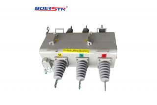
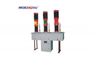
The 20~40.5KV GW7 type disconnector consists of three independent single poles (one main pole and two side poles). Each single pole is composed of a base, insulators, a main conductive part, a transmission system and an earthing switch (when required).
The base is welded by channel steel and steel plates, with a rotating bearing base installed in the middle. The inner cavity of the channel steel on the main pole base is equipped with a transmission connecting rod and an interlocking device for the main blade and earthing blade.
Each pole of the disconnector is equipped with three insulator supports. Each support is assembled by stacking two sections of high-strength solid core porcelain rod insulators. The insulator supports serve to provide insulation between the conductive system and earth, as well as to ensure the mechanical stability of the disconnector under both dynamic and static loads. The lower ends of the insulator supports at both ends are directly fixed to the base, with their upper ends securing the fixed contacts. The lower end of the middle insulator support is fixed to the bearing base, while its upper end secures the conductive blade.
The conductive part consists of fixed contacts and a conductive blade. The fixed contact is composed of a fixed contact base, contact fingers, contact finger springs, a baffle and other components. The conductive blade consists of a conductive tube, a movable contact plate, a transmission device and other components.
3.2 Structure of the earthing switch
This disconnector can be equipped with single earthing switch or double earthing switch of the attachable type. The earthing switch consists of an earthing blade (including movable contact, conductive tube and other components), an earthing fixed contact, transmission parts and other components. The earthing fixed contact is installed under the base plate of the disconnector's fixed contact, while the movable contact, conductive tube and transmission parts are attached to the base of the disconnector.
3.3 Interlocking between disconnector and earthing switch
When the disconnector is in the closed position, the interlock in the base frame prevents the earthing switch from closing. Conversely, when the earthing switch is in the closed position, the interlock can also prevent the disconnector from closing.
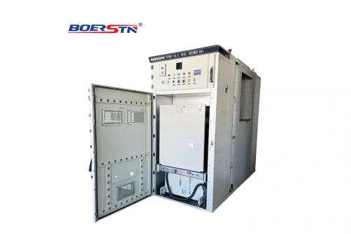
3.4 Motor operating mechanism
CJ6-Ⅰtype motor operating mechanism is an outdoor power mechanism driven by a three-phase AC motor. It transmits torque to the output shaft of the mechanism through a reduction device consisting of gears, a worm wheel and a worm. The mechanism is equipped with an auxiliary switch and a manual device for manual opening and closing operation. Components such as a heater, a lighting lamp and a manual locking switch can also be installed to facilitate user operation.
CS17 type manual operating mechanism is operated by hand via the handle to transmit torque to the output shaft of the mechanism. The mechanism is equipped with an auxiliary switch and has a padlock hole.
4 Operating principle
4.1 Operating principle of the disconnector
When the disconnector is being closed, the motor operating mechanism drives the rotating shaft installed in the base frame of the main pole to rotate approximately 90° through a coupling, a clamp and a vertical connecting rod. A four-bar linkage composed of a crank arm and connecting rods then drives the bearing base to rotate the middle post insulator approximately 115°, which in turn causes the conductive blade to first rotate approximately 70° in the horizontal plane. When the conductive blade is stopped by the fixed contact, the conductive tube further rotates approximately 45° around its own axis, bringing the movable contact plate to an upright position and compressing the fixed contact fingers to establish contact pressure, ensuring reliable contact between the movable contact plate and the fixed contact fingers, thus completing the closing operation.
The opening operation is the reverse of the closing process.
The driving crank arm on the driving main pole is connected to the crank arms of the two driven poles via an inter-phase horizontal connecting rod, enabling the three-pole disconnector to perform opening and closing operations synchronously.
4.2 Operating principle of the earthing switch
The earthing switch features a two-step operating structure. During closing, the manual operating mechanism drives the horizontal rotating shaft of the earthing blade to rotate 90° through a coupling, a clamp, a vertical connecting rod and a spatial four-bar linkage inside the base of the disconnector. The horizontal rotating shaft of the earthing blade then drives a double four-bar linkage in the vertical plane, causing the earthing blade conductive tube to first rotate upward approximately 90° in the vertical plane. After contacting the fixed contact, it changes to an upward linear motion, with the movable contact inserted into the fixed contact, thus completing the closing operation.
The opening operation is the reverse of the closing process. The earthing blade first moves downward linearly to withdraw the movable contact from the earthing fixed contact, then rotates downward 90° to the horizontal position, forming a clearly visible vertical break with the earthing fixed contact above. The driving crank arm on the driving main pole is connected to the crank arms of the two driven poles via an inter-phase horizontal connecting rod, enabling the three-pole earthing switch to perform opening and closing operations
4.3 Operating mechanism
4.3.1 The operating principle and operation method of the CJ6 Ⅰ type motor operating mechanism are detailed in its installation and operation manual.