


Key Features
a) All secondary control components are located directly at the front of the operating mechanism , making inspection and maintenance convenient;
b) Modular functional unit design with a rational structural layout , facilitating maintenance and servicing;
c) Fewer parts , simple structure , and easy operation;
d) The cam directly drives the main shaft to rotate , resulting in high transmission efficiency;
e) Based on a new design concept , no adjustment of latching engagement is required ;
f) Long-life design: mechanical life of 30 ,000 operations for low-current applications and 20 ,000 operations for high-current applications; maintenance-free for 10 ,000 operations , meeting the requirements of Class M2;
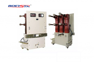
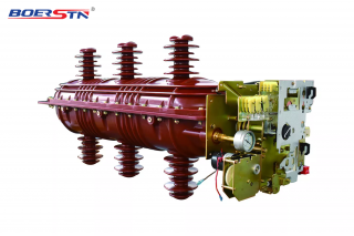
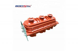
g) The mechanism may be fitted with either assembled insulating cylinders or solid-sealed pole main-circuit components;
h) When used at altitudes of 2000 m and below, the insulation requirements can be met without replacing any parts;
I) Direct interchangeability can be achieved with ZN63A (VS1)-12 and VD4-12 products .
Service Conditions
a) Altitude: areas at 1000 m and below.
b) Ambient temperature: not higher than +40 ° C and not lower than -15 ° C (storage and transportation at - 30 ° C are permitted) .
c) Relative humidity: daily average not exceeding 95% , monthly average not exceeding 90%; saturated vapor pressure , daily average not exceeding 2 .2 × 10- 3 MPa and monthly average not exceeding 1 .8 × 10- 3 MPa . Condensation may occur when the temperature drops sharply during periods of high humidity.
d) Seismic intensity: not exceeding magnitude 8.
e) The installation site shall be free from dripping water, steam , flammable gas , fire hazards , explosion hazards , chemical corrosion , and severe vibration .
Technical Data
Main Technical Data of the VS1(ZN63A)- 12 Series Indoor Vacuum Circuit Breaker
|
No . |
Parameter |
Unit |
Data |
|||||||
|
1 |
Rated voltage |
Kv |
12 |
|||||||
|
2 |
Rated frequency |
Hz |
50 |
|||||||
|
3 |
Rated insulation level |
1 min power-frequency withstand voltage |
Kv |
42 |
||||||
|
Rated lightning impulse withstand voltage |
Kv |
75 |
||||||||
|
4 |
Rated current |
A |
630 |
1250 |
1600 |
2000 |
2500 |
3150 |
4000 |
|
|
5 |
Rated short-circuit breaking current Rated short-time withstand current (r. m .s .) |
KA |
20 |
20 |
|
|
|
|
|
|
|
25 |
25 |
|
|
|
|
|
||||
|
|
31.5 |
31.5 |
31.5 |
31.5 |
31.5 |
31.5 |
||||
|
|
40 |
40 |
40 |
40 |
40 |
40 |
||||
|
6 |
Rated short-circuit making current (peak) Rated peak withstand current |
KA |
50 |
50 |
|
|
|
|
|
|
|
63 |
63 |
63 |
|
|
|
|
||||
|
|
80 |
80 |
80 |
80 |
80 |
80 |
||||
|
|
100 |
100 |
100 |
100 |
100 |
100 |
||||
|
7 |
Number of operations at rated short-circuit breaking current |
times |
50 ,20* |
|||||||
|
8 |
Rated short-time withstand duration |
s |
4 |
|||||||
|
9 |
Rated operating sequence |
|
O-0 .3 s-CO- 180 s-CO* |
|||||||
|
10 |
Mechanical life |
times |
10000 |
|||||||
|
11 |
Rated single capacitor bank breaking current |
A |
400/630 |
|||||||
|
12 |
Rated back-to-back capacitor bank breaking current |
A |
400 |
|||||||
Note:
1 . When the rated short-circuit breaking current is ≤ 31 .5 kA , the number of operations at rated short-circuit breaking current is 50.
When the rated short-circuit breaking current is >31 .5 kA , the number of operations at rated short-circuit breaking current is 20.
2 . When the rated short-circuit breaking current is 40 kA , the rated operating sequence is: O-180 s-CO-180 s-CO.
3. Items 11 and 12 are rated parameters to be provided when required.
Mechanical Characteristics of the Circuit Breaker After Assembly and Adjustment
|
No . |
Parameter |
Unit |
Data |
||||
|
1 |
Contact opening distance |
mm |
9±1 |
||||
|
2 |
Contact travel |
mm |
3.5±0 .5 |
||||
|
3 |
Three-phase opening/closing simultaneity |
ms |
≤2 |
||||
|
4 |
Closing contact bounce time |
ms |
≤2 |
||||
|
5 |
Centre-to-centre phase spacing |
mm |
210±1 .5(275±1 .5) |
||||
|
6 |
Rated short-circuit breaking current |
kA |
20 |
25 |
31.5 |
40 |
50 |
|
7 |
Closing contact pressure |
N |
2000±200 |
2400±200 |
3100±200 |
4500±200 |
6000±200 |
|
8 |
Average opening speed |
m/s |
1.2±0 .2 |
||||
|
9 |
Average closing speed |
m/s |
0.7±0 .2 |
||||
|
10 |
Opening time |
ms |
≤50 |
||||
|
11 |
Closing time |
ms |
≤70 |
||||
|
12 |
Main circuit resistance per phase |
µΩ |
≤50 (630 A- 1250 A) ≤45 (1600 A) ,≤35 (2000 A) ≤25 (2500 A and above) |
||||
|
13 |
Permissible wear thickness of moving and fixed contacts |
mm |
≤3 |
||||
Technical Data of Closing Coil and Opening Coil
|
|
Closing/Opening Coil |
Interlocking Coil |
Anti-pumping Relay |
|||
|
Rated operating voltage (V) |
DC220 |
DC110 |
DC220 |
DC110 |
DC220 |
DC110 |
|
Coil power (W) |
198 |
198 |
4.4 |
2.7 |
1.0 |
|
|
Rated current (A) |
0.9 |
1.8 |
20mA |
25mA |
9. 1mA |
|
|
Operating voltage range |
85% to 110% of rated voltage |
65% to 110% of rated voltage |
|
|||
Technical Data of Charging Motor
|
Rated voltage (V) |
Rated power (W) |
Normal operating voltage range (V) |
Charging time at rated voltage (s) |
|
DC220 DC110 |
90 |
(0 .8-1. 1) times rated voltage |
≤15 |