Product description
-
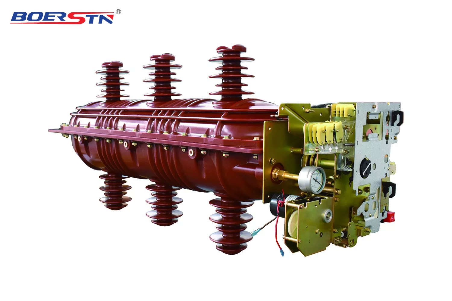
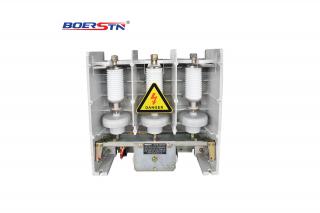
BRFLN36 series indoor high-voltage SF6 load break switch, It is widely used in 36kV electric power distribution system , adopted with SF6 gas as an arc-extinguishing and insulation medium, including the three contactors for switching-on and switching-off and to-ground, and is characteristic in its small volume, its convenient installation and operation and its the great adaptability with surroundings.
-
Indoor high-voltage SF6 load break switch and SF6 load break switch plus fuse combination can function to protect and control the electric equipments for power supply and transformer substations especially being suitable for ring net cabinet, cable branch cabinet and distribution switching substation.
indoor high-voltage SF6 load break switch and SF6 load break switch plus fuse combination are complied with the standards of IEC60265-1-1998, IEC60420 etc.
Service environment
-
a)Air temperature
Maximum temperature: +40℃; Minimum temperature:-35℃
b)Humidity
Monthly average humidity 95%; Daily average humidity 90% .
c)Altitude above sea level
Maximum installation altitude: 2500m
d)Ambient air not apparently polluted by corrosive and flammable gas, vapor etc.
e)No frequent violent shake
Main Specification & Technical Data
|
No
|
Item
|
Unit
|
Parameter
|
|
1
|
Rated voltage
|
kV
|
36
|
|
2
|
Rated frequency
|
Hz
|
50/60
|
|
3
|
Rated current
|
A
|
630
|
|
4
|
1min Power frequency
withstand voltage
|
wet
|
kV
|
95
|
|
dry
|
kV
|
110
|
|
5
|
Lightning impulse withstand voltage
|
kV
|
185/215
|
|
6
|
Rated short circuit breaking current (peak)
|
kA
|
50
|
|
7
|
Rated active load and close circuit breaking
current
|
A
|
50
|
|
8
|
Rated transferring current
|
A
|
1000
|
|
9
|
Rated short circuit making current (peak)
|
kA
|
50
|
|
10
|
Rated cable(line) charging breaking current
|
A
|
50 and 10
|
|
11
|
Cable charge breaking current in earthing fault
|
A
|
20
|
|
12
|
Rated withstand current (peak)
|
kA
|
50
|
|
13
|
Short time withstand current (2s)
|
kA
|
20
|
|
14
|
Mechanism life
|
times
|
2000
|
Note: For short circuit breaking and peak current is based on Fuse plus combination.
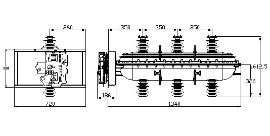
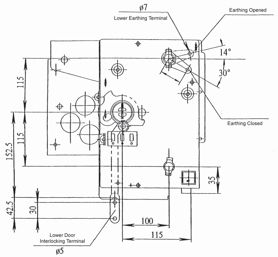
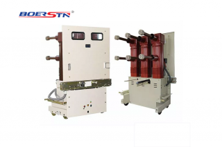
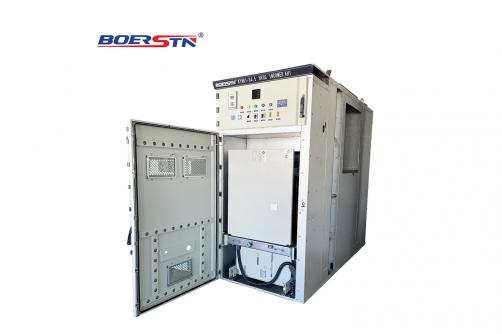
Outline Dimension& installation sizes
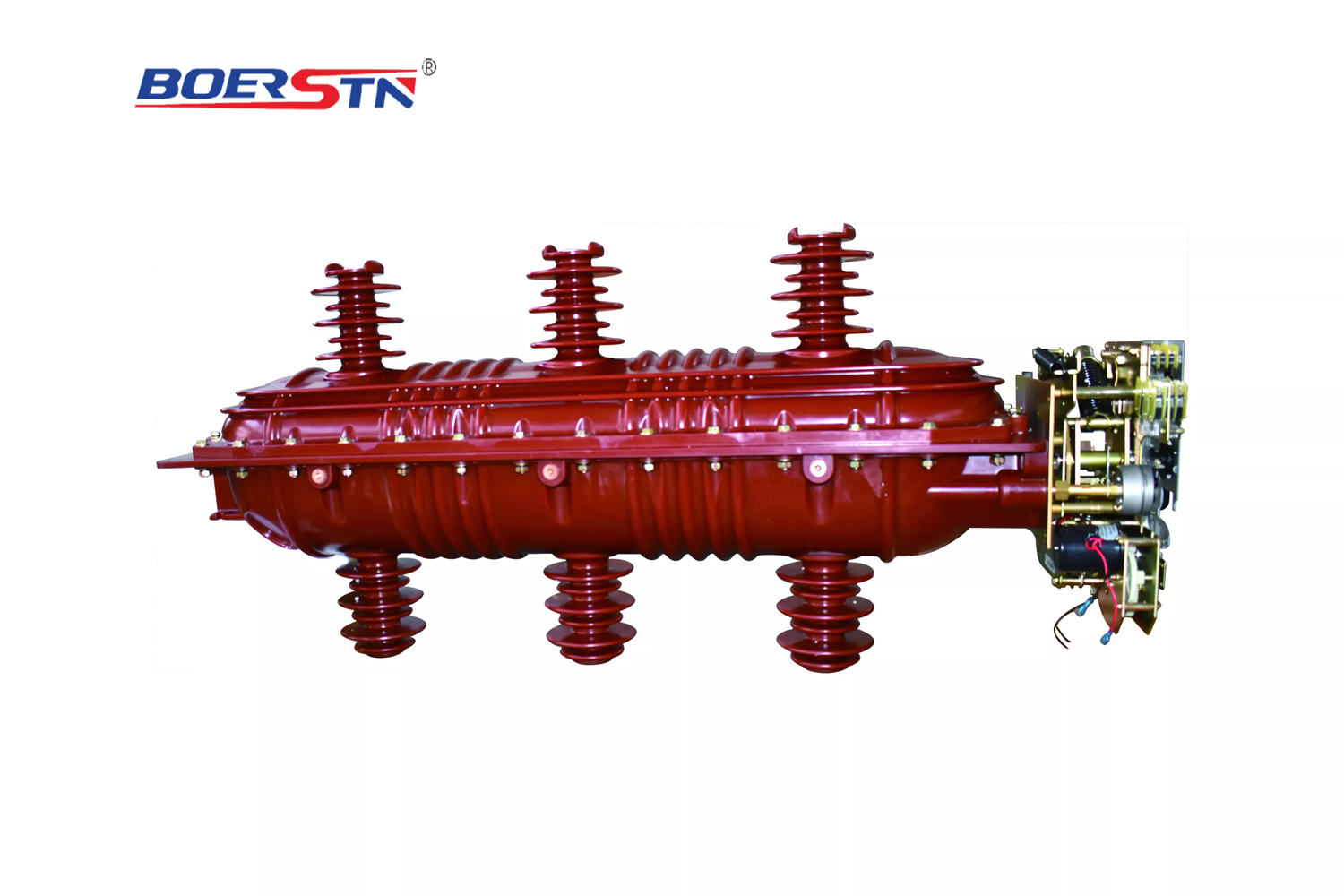
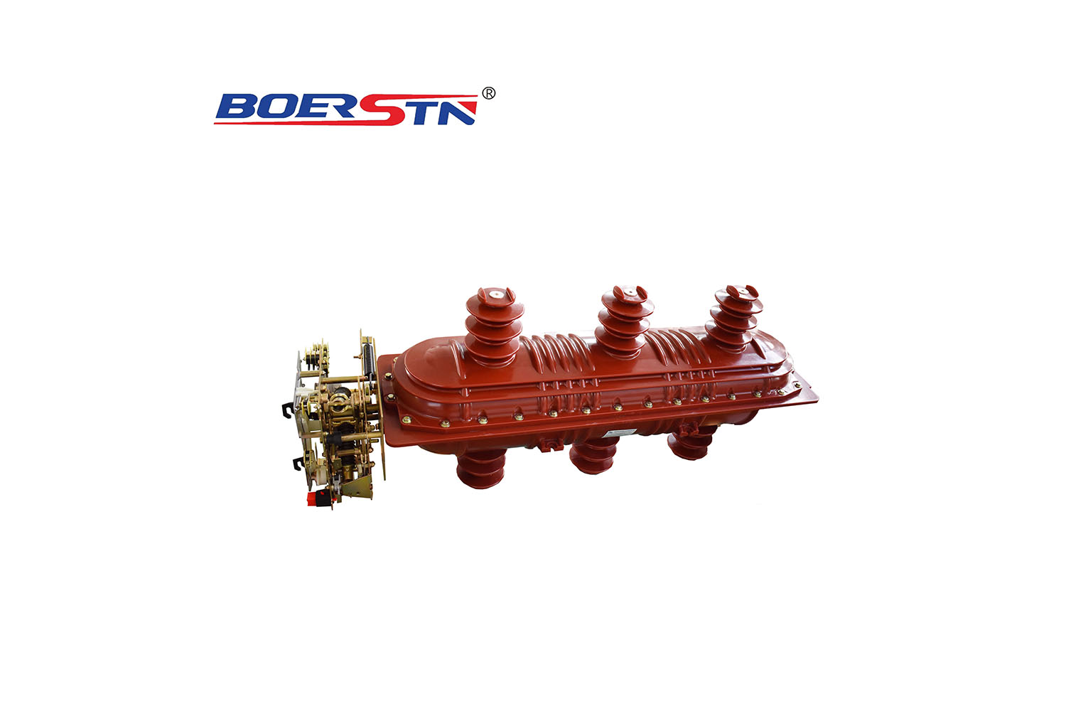
1) SF6 load break switch without upper cubicle
Dimenssion view of load break switch
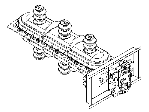
Fig 2) Whole Load break switch outline
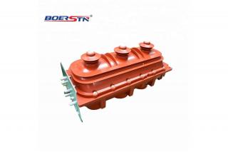
Primary circuit loop of load break switch
-
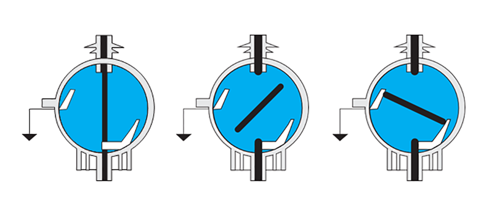
Primary loop of BRFLN36-36 indoor load break switch and its combination is sealed in a epikote casted insulate unit by APG technology, this insulate unit has features of good insulating property, dust and dirts proof, insulate unit contains upper and lower insulate covers, inside charged 1.5bars pressure SF6 gas, the partial siding of lower cover is very thin, it's a protective measure and will burst out in the malfunction, the over pressed gas is released to protect the equipment.
-
SF6 load break switch and its fuse combination has open,close and earth three working position.
Arc extinction
-
BRFLN36-36 load break switch adopts SF6 gas as the medium of arc extinction, when switch on and off, arc occurs and will spin under the magnetic field effect ion by the permanent magnet, cooled by the SF6 gas and extricated finally.
-
This indoor SF6 load break switch and its fuse combination works with spring type operating mechanisms A and K, BRFLN36-36 load break switch equipped with the K spring operating mechanism is applied as the incoming control unit, while that equipped with A mechanism is applied as the outgoing protective unit and transformer unit.
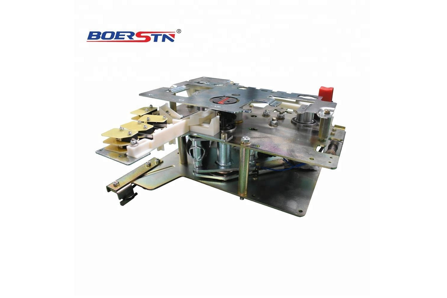
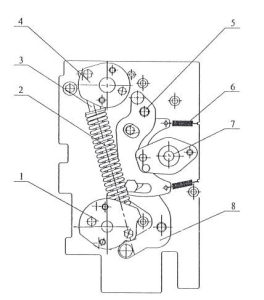
1)"K" Type Spring Operating Mechanism
Working principle of K type spring operating mechanism is spring press and release( see fig 1. it's in off position)
A)Earthing operation
Driven by the handle, upper crank arm 4 rotates and presses spring 2 to store energy, when the max energy reached continue rotate the crank arm, the energy storage spring starts to release energy and drive the upper trigger, enables the connecting bar to drive the crank arm, crank arm rotates and drives the moving contactor for earthing.
B)Switch on operation
Driven by the handle, lower crank arm 1 rotates, presses spring 2 to store energy, when the energy released, it drives the trigger 8,enables connecting bar to drive the crank arm, crank arm rotates and drives the moving contactor and load break switch turns on.
C)Switch off operation
Rotate the main shaft crank arm counterclockwise by the handle, release the energy storage spring and the load break switch turns off.
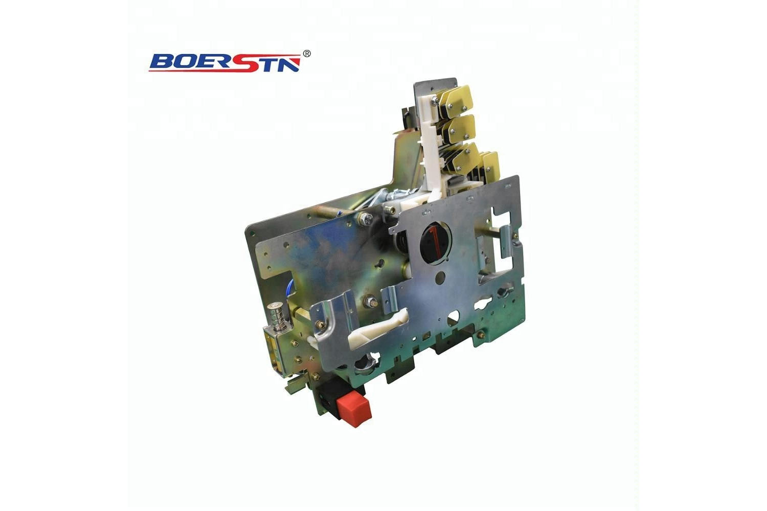
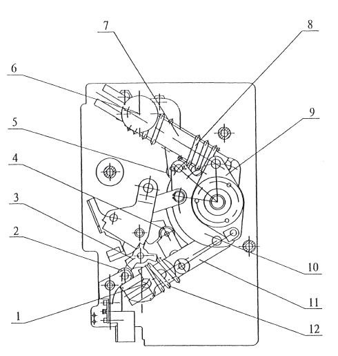
2)"A" Type Spring Mechanism
Working principle of A type mechanism is same as K type, in addition, it has fuse striker unbuckle function. For A type mechanism, electromagnetic unbuckle is also available on customers requirement.(see fig 2)
A)Switch on operation
Driven by the handle, lower crank arm 1 rotates to presse switch on spring 12 and switch off spring 8 at the same time, to provide sufficient energy required by switching off. when the lower crank arm 1 buckles the pin and drives trigger to move, it makes the lower roller wheel unbuckled, and release the switch on spring and load break switch turns on.
B)Switch off operation
Press the switch off button or push the unbuckle pin 2 by the fuse striker, release the spring and load switch turns off.
C)Earthing operation
Earthing operation of A type mechanism is same as that of K type.
3)K type and A type operating mechanism can be operated manually or motorized on request.
Notice: only when the load break turns off, can turning on and earthing operation be done.
1-lower crank arm
2-energy storage spring
3-guider bar
4-upper crank arm
5-upper trigger
6-pull spring
7-main shaft crank arm
8-lower trigger
Fig 1: K type spring operating mechanism
1-lower crankshaft
2-unbuckle pin
3-cam
4-lower roller wheel
5-upper roller wheel
6-upper crankshaft
7-upper guider bar
8-switch off spring
9-energy storage crank arm
10-main shaft crank arm
11-lower guider bar
12-switch on spring
Fig 2: A type mechanism ( switch on position)