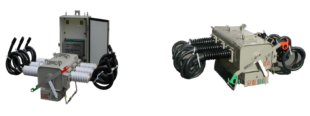
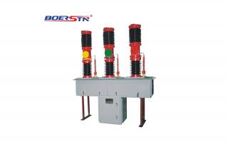
6.1.Overview of switch and controller (Type:iDA-GRcA-6)
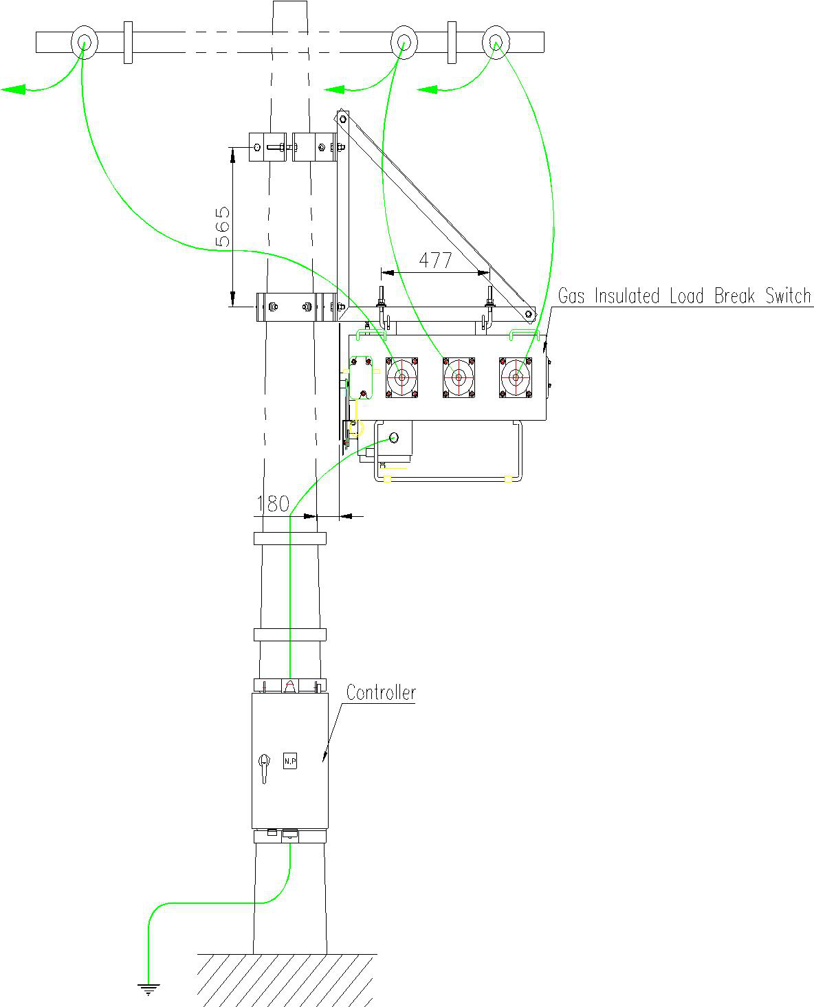
Fig.5) Connection Diagram
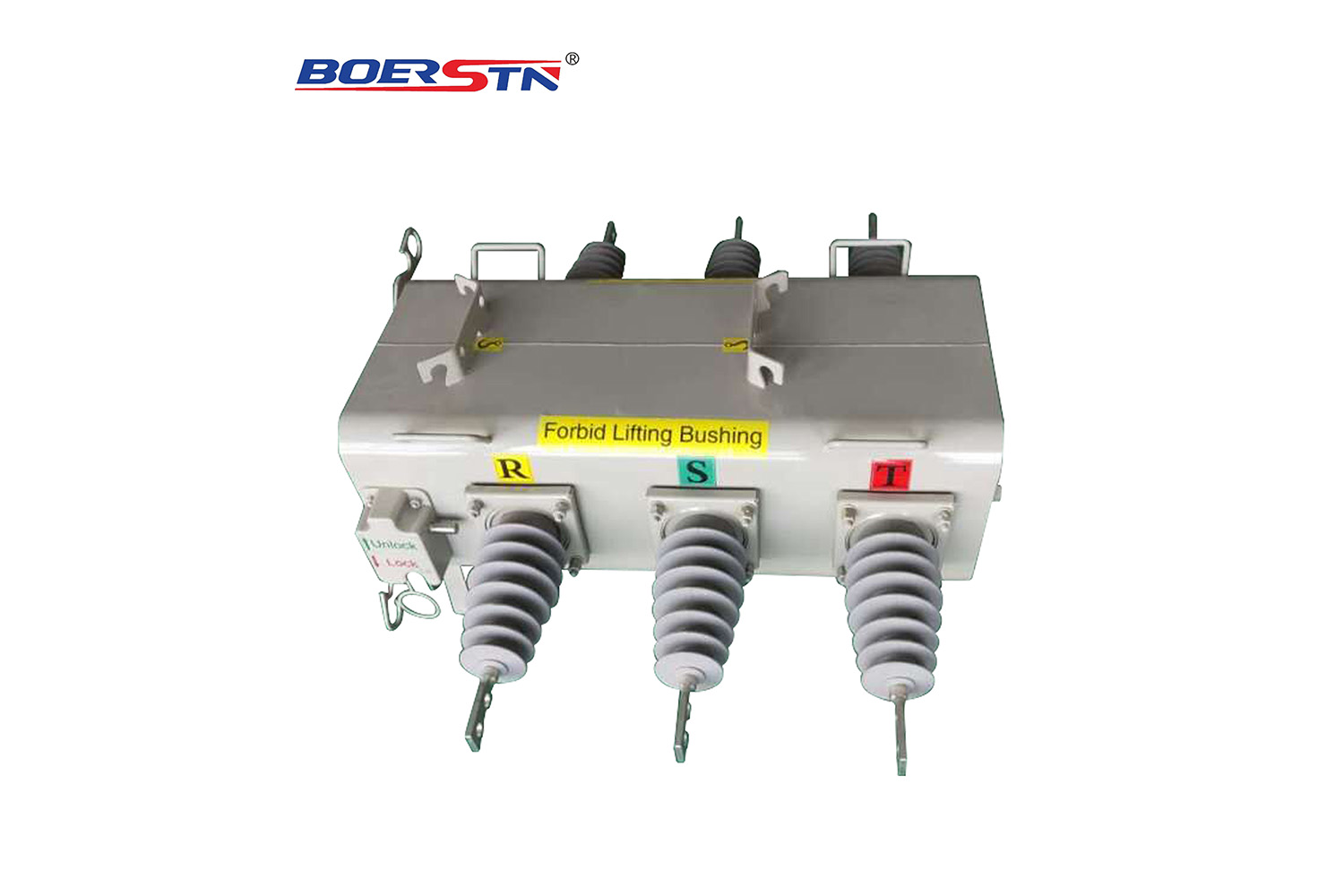
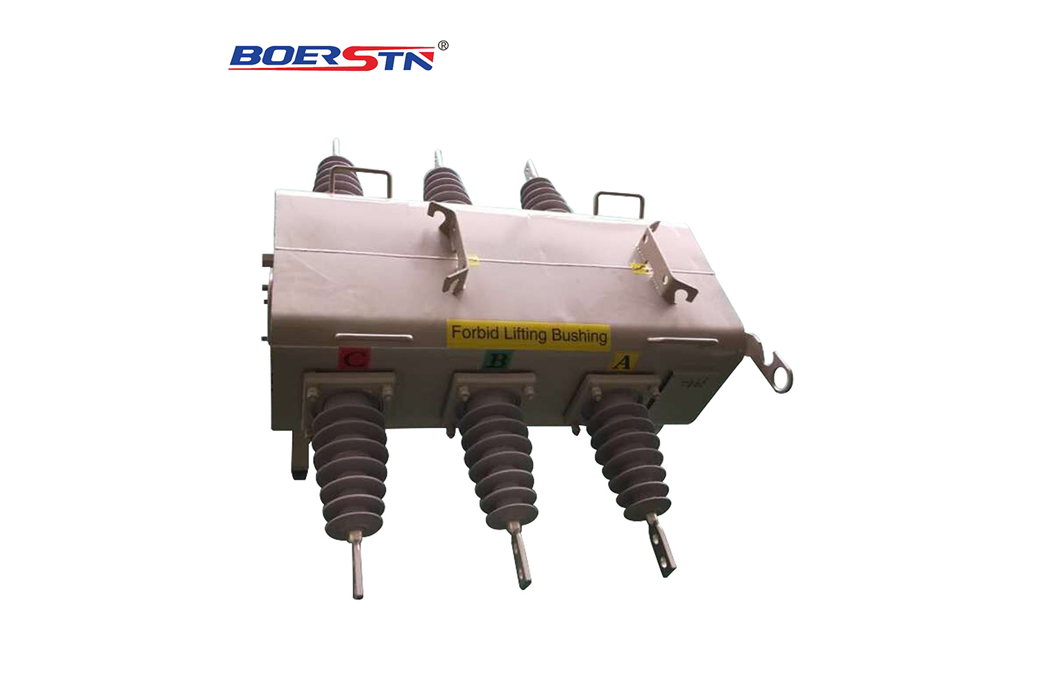
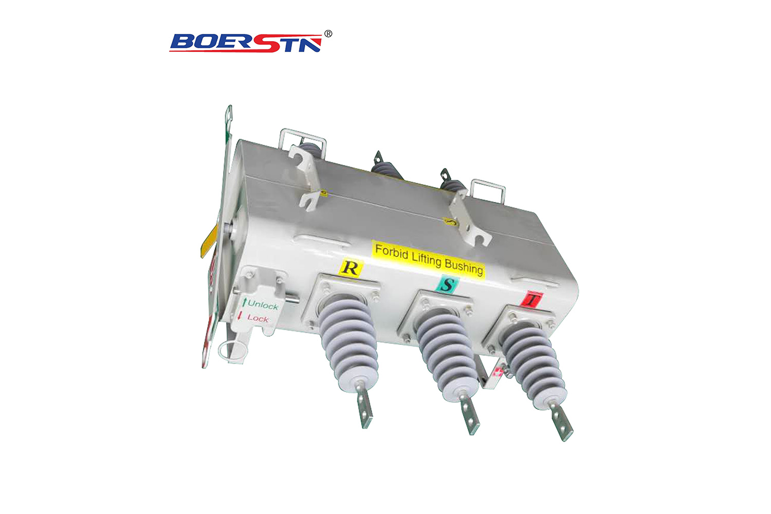
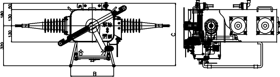
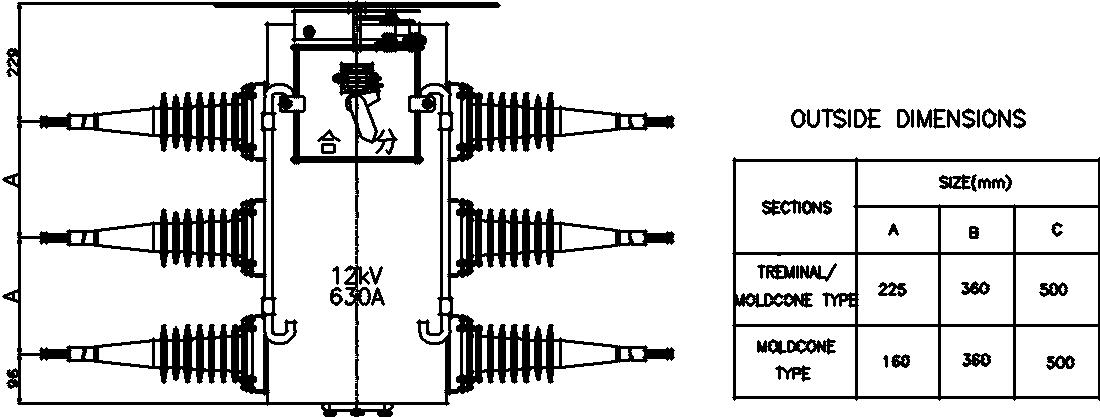
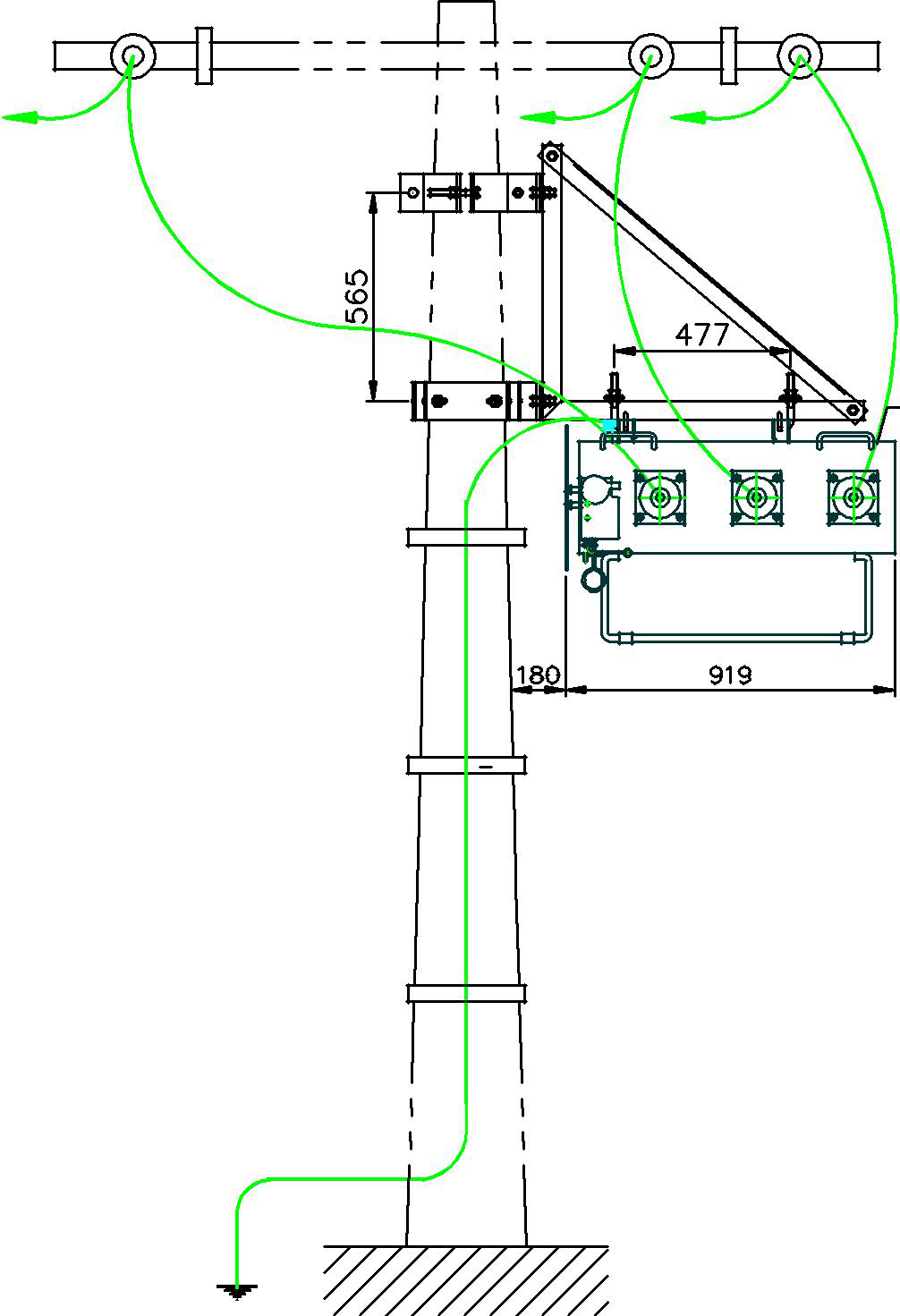
6.2. Overview and Dimensions of switch
|
Dimension(mm)
|
Installation Dimension(mm)
|
Packingsize(mm)
|
Creepdistance of bushing(mm)
|
|
|
A
|
B
|
C
|
Length×Width
|
Length×Width×high
|
|
|
12KV
|
225
|
435
|
500
|
500×390
|
1100×900×700
|
556
|
|
24KV
|
300
|
435
|
500
|
500×390
|
1300×1100×700
|
840
|
|
40.5KV
|
350
|
435
|
500
|
700×390
|
1400×1200×700
|
1250
|
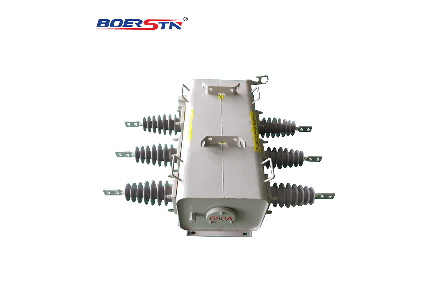
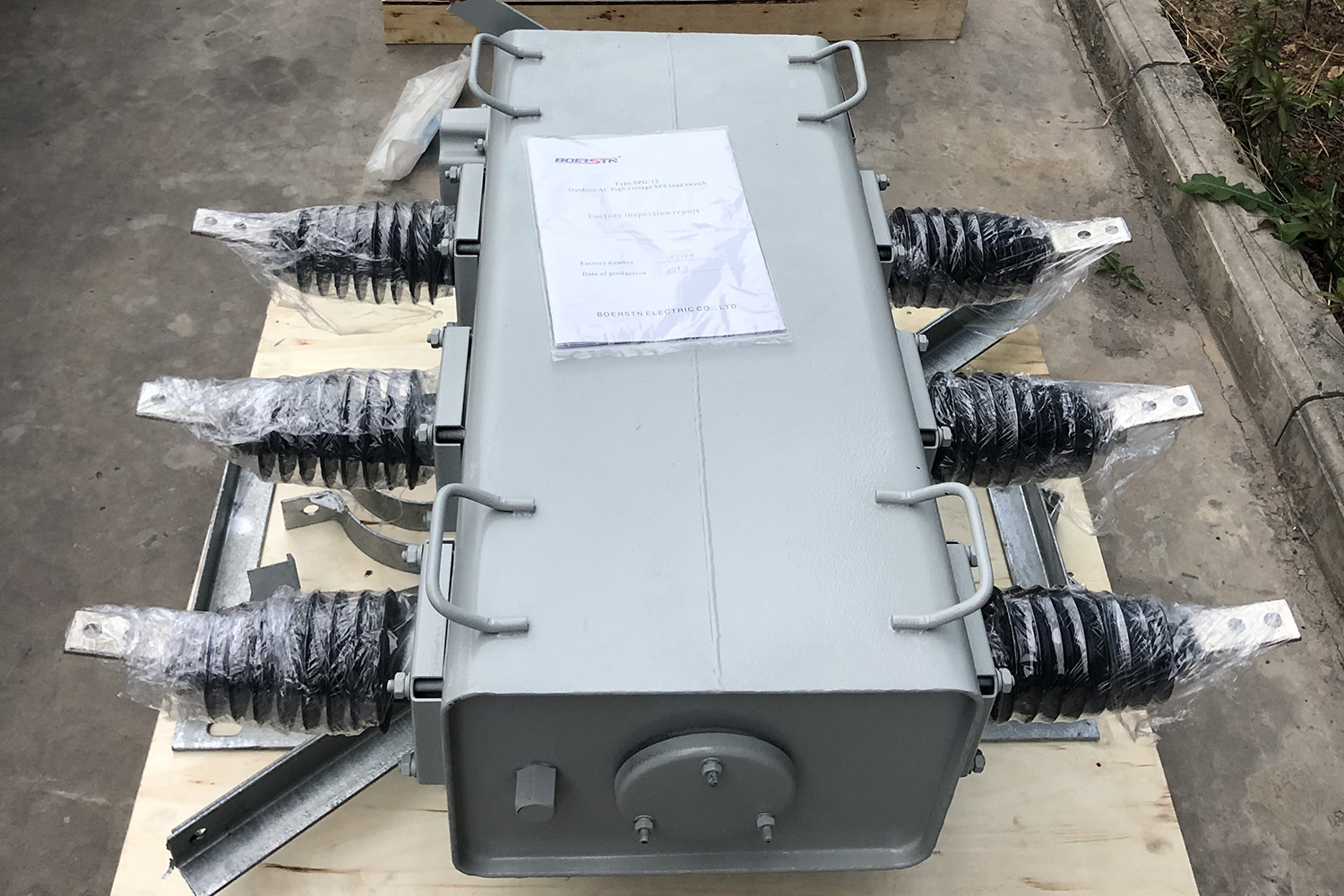
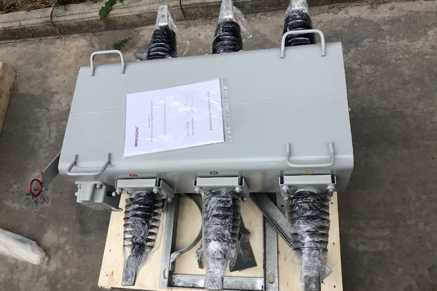
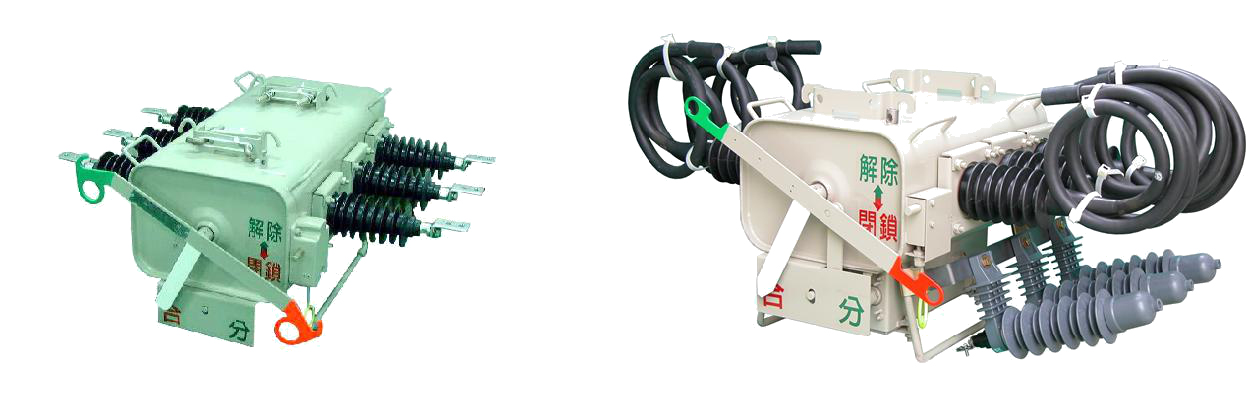
6.3.LBS Main Body.
6.3.1.SF6 gas insulated switch is a three-phase gang-operation switching device designed for cable and overhead line sectionalizing applications on distribution systems, being operated manually at site or remotely from control center.
6.3.2.Switch tank shall completely sealed by welding and/or rubber -seal gasket, and all components shall be assembled in a welded stainless steel tank.
6.3.3.Switch tank shall be designed to withstand internal pressure without affecting the performance of the switch.
6.3.4.The enclosure of tank is used of the material of the cold rolling stainless steel of over 3mm (STS 304L) or more than equivalent to be able to endure against inner gas pressure and is treated for completely anticorrosive by coating of resin over the enclosure.
And the enclosure is the rustless structure by separating bottom side over 10 mm from ground.
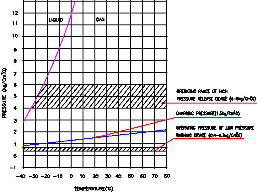
Fig. 6) Temperature-pressure characteristic curve
6.4.1.SF6 gas used for Pole-LBS is high-pure products and is designed and manufactured to keep below 1,000ppm for water content in gas of main body during loaded current switching.
6.4.2.Considering application temperature range and gas leakage of gas in Pole-LBS, rated pressure, maximum pressure, maximum guaranteed pressure and gas pressure drop locking pressure are as shown in attached
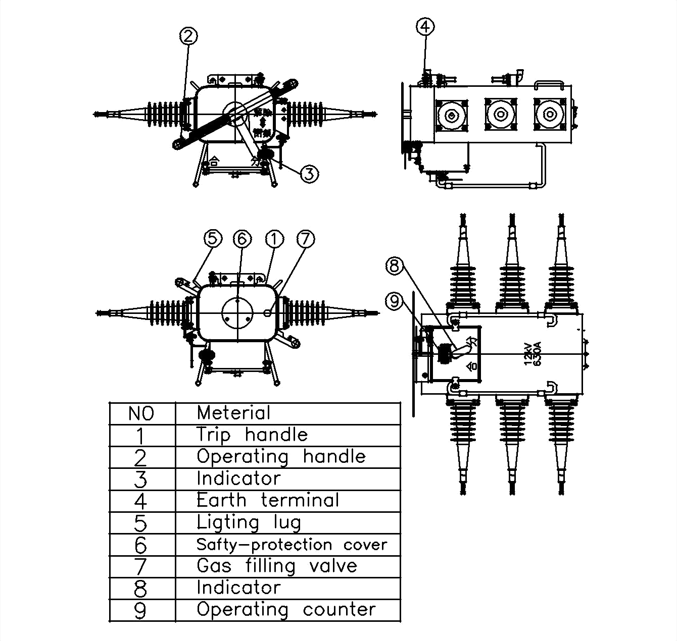
6.5.The factory built-in accessories
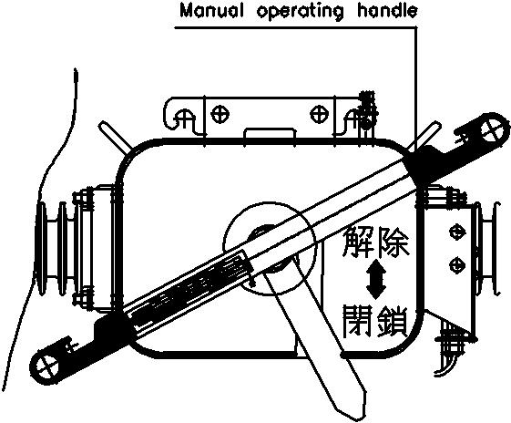
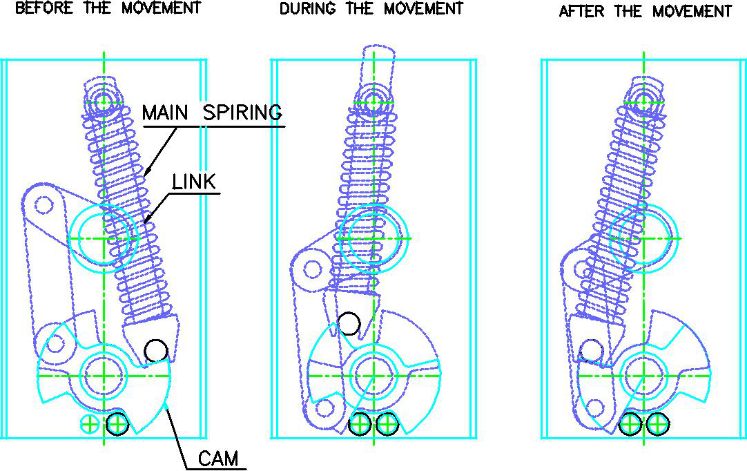
6.5.1.Manual operating handle
The LBS is to be safely and easily operated by hot stick for
high voltage, and is the structure being completed the on or
off by one time operation.
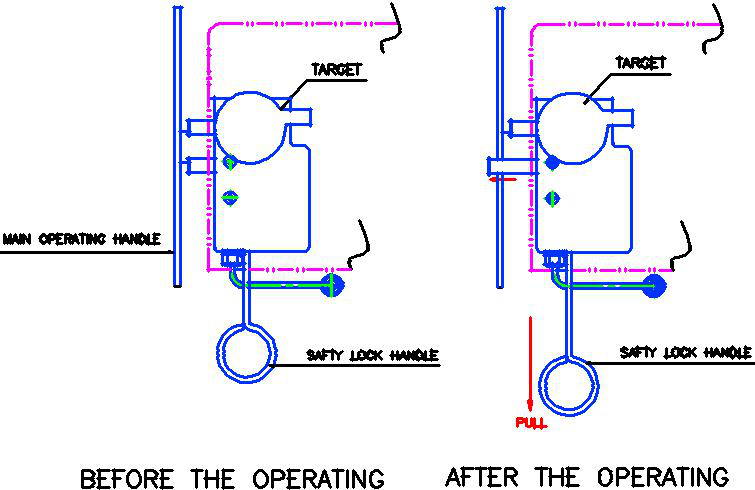
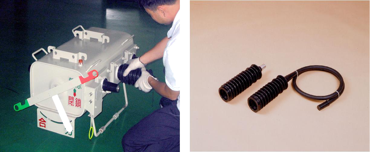
6.5.2.Safety lock device
It is possible to lock the operation apparatus in the position of On or Off, its structure is impossible to electrically and mechanically operate to on or off position in case of locking.
Dwg.2) Safety lock device
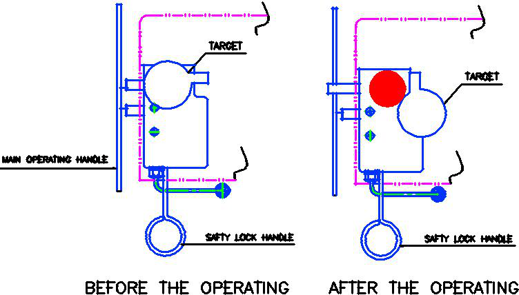
6.5.3.Contact position Indicator
The color coded main contact position indicator(green-open, red-closed) is easily visible from the ground.
6.5.4.Low pressure warning device
The automatic locking apparatus is equipped to be impossible for electrical and mechanical On-Off operation in the state of causing a risk when On-Off operation due to the pressure drop(0.4~0.7㎏ /㎠ .G) and there is the indicator being able to easily certify by the operator
Dwg.4) Low pressure warning device
6.5.5.High pressure release device
The gas release apparatus with the structure preventing the demolition of the tank for the safe of operator and common people and that the inner apparatus is not spread to outside in case of sudden rising of the inner gas pressure of the main body due to the internal trouble is equipped.
Dwg.5) High pressure release device
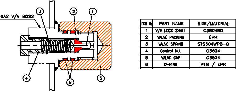
6.5.6.Gas filling valve
The valve is equipped to instill gas in the tank of the main body
Dwg.6) Gas filling valve
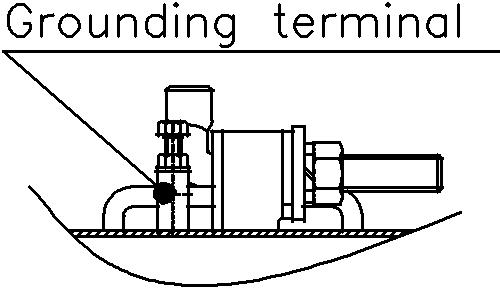
6.5.7.Grounding Terminal
Its structure is easily connect with the copper cable of 22mm² ~ 38mm² without the extra auxiliary clamp
Dwg.7) Grounding terminal
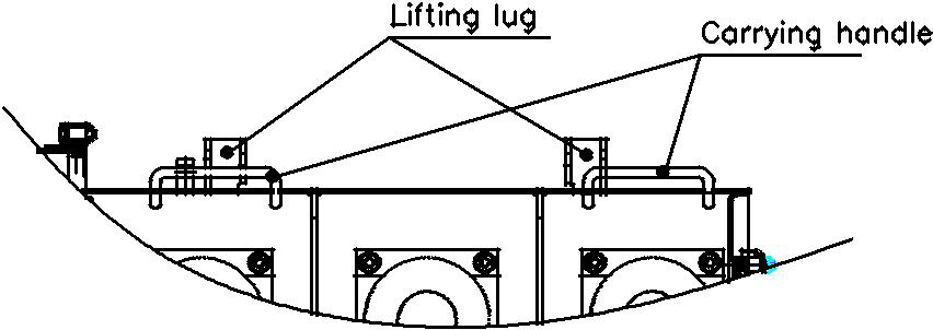
6.5.8.Lifting lug
The four (4) Handle for transportation are installed on the upper side of the main body
Dwg.8) Lifting lug
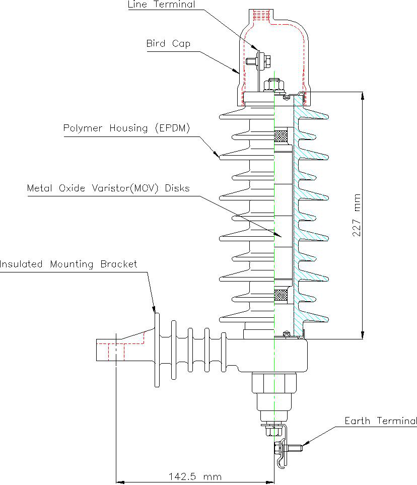
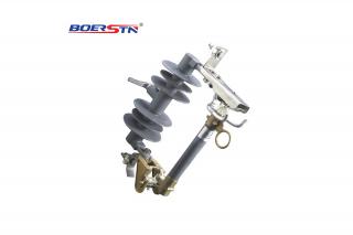
6.6. Polymer Rubber Bushing
Fig.8) Rubber Terminal &
Rubber Mold-cone
6.6.1.The material of the bushings is as of the epoxy and EPDM rubber or porcelain.
6.6.2.Features of the epoxy and EPDM rubber
-Light weight and easy to handle.
-Unbreakable.
-Integrated design with moldcone.
-Excellent Mechanical Strength.
-Self cleaning function.
-Short installation time and maintenance.
6.7.External connection terminal
6.7.1.The insulated cable for high voltage that has the flexibility and weather proof for the mold cone lead wire method is used, the nominal area and composition of core are over 125㎟ (159/1.0) for 400A and over 200㎟ (19/14/1.0) for 630A, and the length required is over 2m.
6.7.2.In case of the terminal type, allowable current for sectional area of the conductor is 630A.
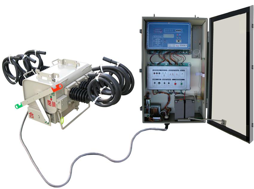
Dwg.9) Operating Mechanism
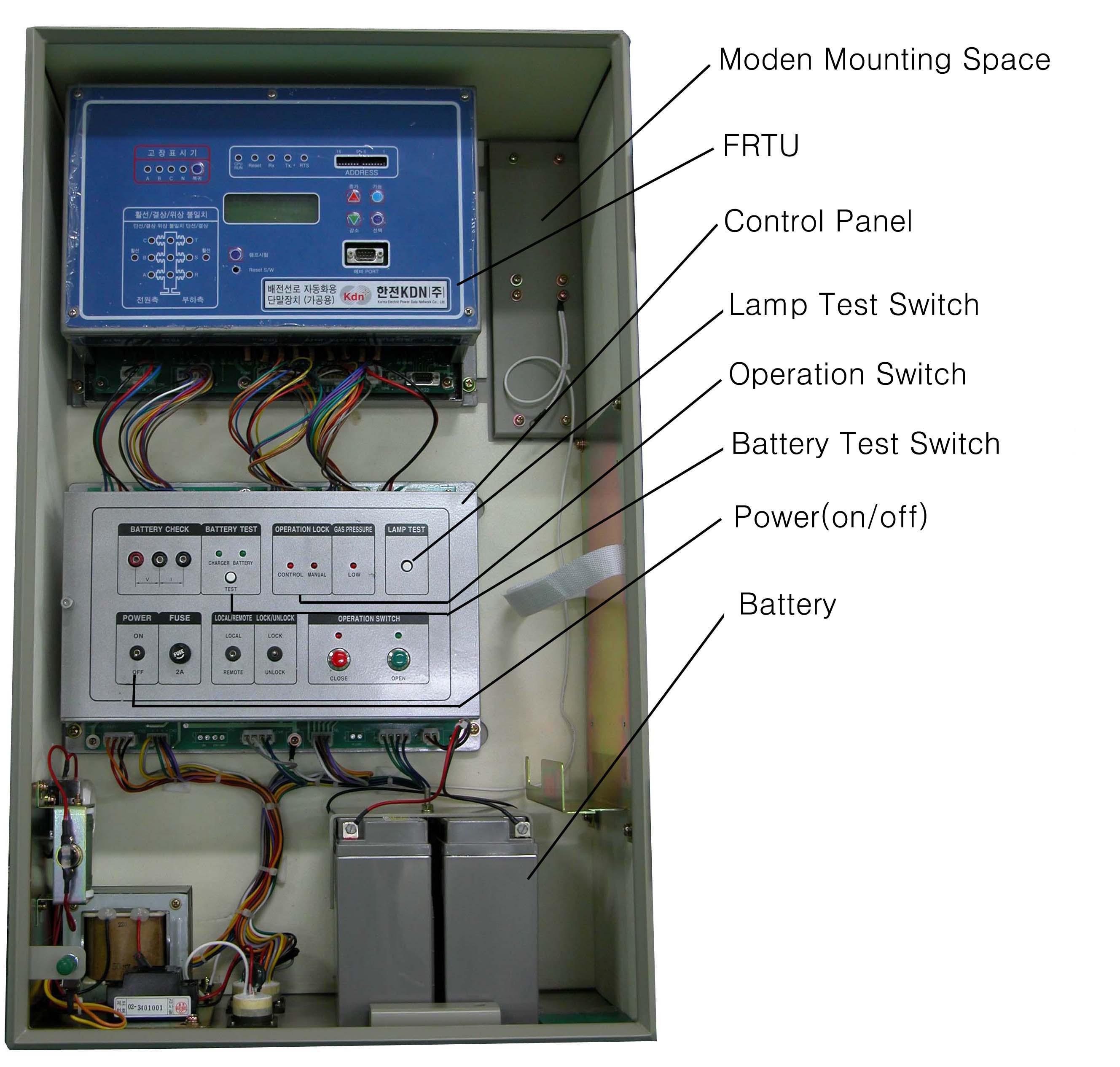
Fig.9) Overview of Controller
7.1. The control box shall be manufactured by using stainless steel plate over than 1.5mm thickness and shall have the installing clamps to easily install at the concrete pole
7.2.The controller can operate the pole-LBS by locally or remotely.
7.3.The controller monitors the SF6 gas pressure of pole-LBS.
If gas pressure falls below a pre-set threshold(0.4-0.7kg/㎠
.G), then an SF6 low pressure red lamp is lit on the local panel, and electrical and manual operations are locked out.
7.4. The control box contains the following operation and display device
7.4.1.Operation switch: Close, Open
7.4.2.Operation selecting switch: local/remote
7.4.3.Operation locking switch: Lock/unlock
7.4.4.Rechargeable battery test terminal and test switch
7.4.5.Lamp test switch
7.4.6.Control power switch (on/off) and fuse
7.4.7.LED
-Display of main contact condition: close(red), open(green)
-Display of locking for low gas pressure
-Display of locking for switching operation (Control box/main body)
-Display of condition of recharging part and rechargeable battery
7.5.The rechargeable batter and charging devices are as follows
7.5.1. Rechargeable battery for control power
- This is DC 24V and rechargeable. This makes more than 50 switching operations by just recharging once and contains the rechargeable battery, which has capability that lasts more than 24hour control under failure of AC power.
7.5.2. Rechargeable battery and charging device
- The recharging current necessary for the battery by ambient temperature is controlled automatically. It contains protection circuit from the over-charge and over-discharge.
7.5.3. Test terminal of rechargeable battery
-Terminal for test and the display of charge condition of article are equipped so that the conditions of the battery voltage and of the charging device can be checked under loading/unloadin condition.
7.5.4. Connecting diagram
Dwg.10) Connecting diagram on the lug terminal
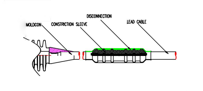
Type #1) Insulation Piercing Connector
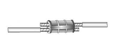
Type #2) Compression Sleeve
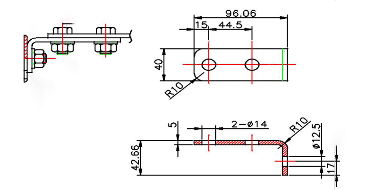
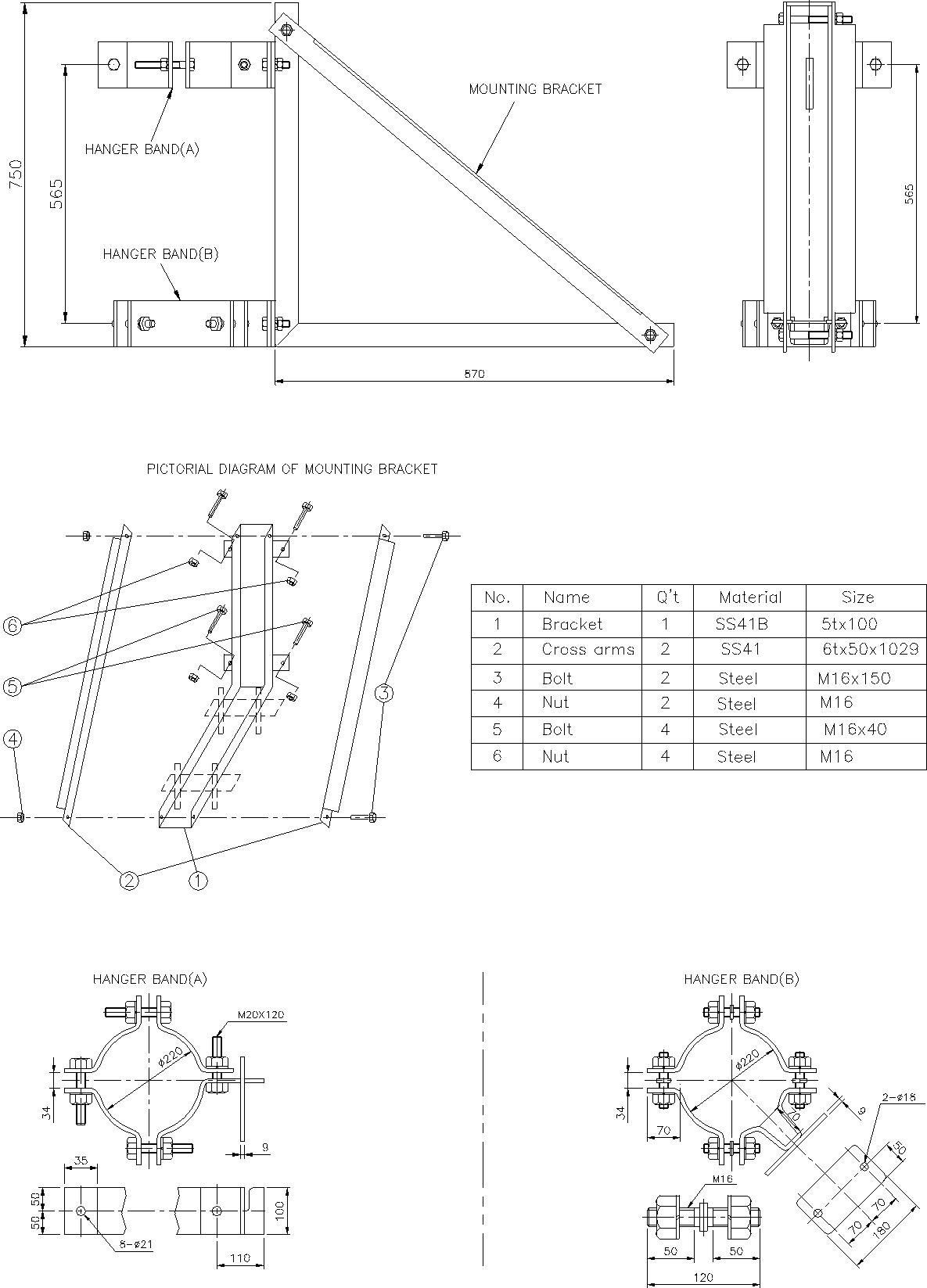
Detail drawing for Pole Mounting Bracket
9.Connection of the cable to the switchgear
9.1.Switch Mounting and Dimensions (Automatic Type)
Dwg.11) Switch Mounting and Dimensions
9.2. Switch Mounting and Dimensions (Manual Type)
Dwg.12) Switch Mounting and Dimensions
10.1.Overview and Dimension
10.2. Rating
|
Descriptions
|
Rating
|
|
Rated Arrester Voltage
|
24 kV
|
|
Nominal Discharge current, 8/20 μs
|
5 kA
|
|
Max. Continuous Operating Voltage
|
10.2 kVrms
|
|
Residual Voltage, 8/20 μs
|
64 kV (at 5kA)
|
|
High Current Withstand, 4/10 μs
|
65 kA
|
|
Applicable Design and Test Standard
|
IEC 60099-4
|