Low Voltage Withdrawable Motor Control Center( MCC)
MCC series of low voltage withdrawable motor switchgear is a kind of combination type motor panel,its technology reaches  international levels. It is suitable for control motor starting ,transformer station, electric power plant, petrochemical industry, metallurgical steel rolling ,traffic energy,light and textile industry ,and residence community, high building ..etc. As electric power energy conversation ,distribution & controlling for power distribution equipments of AC 50/60Hz rated serv
Share This Product:
  • product details
  • Switchgear Structure Characteristic
  • Switchgear Installation

Service Conditions

  • 1. Ambient temperature:-30℃ ~ +50℃,and measuring average RH within 24 hours ≤+50℃;
    2. Altitude: Not exceed 2000m above sea level;
    3. Ambient humidity: Daily average RH ≤ 95%; Monthly average RH ≤ 90%
    4. Earthquake intensity: ≤ Degree 8
    5. Water vapor pressure:Daily average RH ≤ 2.2kPa; Monthly average RH ≤ 1.8kPa;
    6. Ambient environment: no fire, explosion danger, serious pollution, chemical corrosion and severe vibration place

Basic technical parameters

1.Electric performance

Rated insulation voltage

690V(1000)V

Rated working voltage

380V,400V,690V

Maximum working current of main bus

6300A

Rated withstand current of main busbar

100kA/1s

Main busbar rated peak withstand current

220kA/0.1s

Maximum operating current of branch distribution bus (vertical bus)

2000A

Peak current of distribution bus (vertical busbar):


Standard type

105kA(Max)/0.1s

Reinforced type

176kA(Max)/0.1s

Protection level

IP41

Cabinet structure

  • Its basic structure is an assembly of C type profiles which made from plate bending with E=25 module installation hole. The whole cabinet and inner compartments are purification treatment of zinc plating. The door panels and side panels are electrostatic sprayed.The cabinet basic structure is as picture.1 and basic size as picture.2 (table 1 and 2)

Cabinet type

  • 1.Power Distribution Center switchgear (PC): can adopt Emax,MT,3WN,AH,ME series circuit breakers. 2.Motor control center switchgear (GCK、GCS、MNS) : it is the assembly of big & small drawer, every circuit main switch is high breaking moulded case circuit breaker or rotation type load break switch with fuse. Power factor automatic compensation cabinet is with manual or automatic and remote power factor compensation device.

  • A Power distribution center (PC) cabinet


  • Height

    Width

    Depth

    Remark

    H

    B

    T

    T1

    T2

    2200

    400

    1000

    800

    200

    Main bus transfer

    2200

    400

    1000

    800

    200

    F s-1250-2000 ME630-1605

    2200

    600

    1000

    800

    200

    F s-2500

    2200

    800

    1000

    800

    200

    F s-3200 ME2000-3200

    2200

    1000

    1000

    800

    200

    F s-4000 ME3205

    2200

    1200

    1000

    800

    200

    ME4005


  • B Power distribution center (PC) cabinet


  • Height

    Width

    Depth

    Remark

    H

    B

    B1

    B2

    T

    T2

    T2

    2200

    1000

    600

    400

    600

    400

    200

    Single-side operation

    2200

    1000

    600

    400

    1000

    400

    200

    Double-side operation


  • C type composed frame structure (Figure 1)

  • Schematic diagram of cabinet (Fig 2)

Cabinet compartment design

  • 1)Power distribution center (PC).

  • (1)In the PC cabinet ,there has 3 compartments.
    The horizontal busbar compartment is at the back of the cabinet.
    Function unit compartment is at the front of cabinet or the left of cabinet.

    (2)The way of compartment: use steel plate between the horizontal busbar compartment and function unit compartment. Use flame retardant polyphenylene oxide plastic shell between the circuit controlling compartment and function unit compartment.

    (3)Inner installed air circuit breaker ,which can be operated by manual at outside cabinet when the door is closed. To determine whether the circuit breaker is in the test position or in the service position by observing circuit breaker ON-OFF state and the position between door and controlling systems.

    (4)Between the main circuit and auxiliary circuit ,designing the compartments structure to auxiliary electric units like instrument, signal lamps & push buttons etc ,which are fixed on the plastic plate . At the back of this plate, the shell made of flame retardant polyamine foam plastics ,which is separated from the main circuit.

  • 2)Withdrawable type motor control center & small current power distribution center (GCK、GCS、MNS):

  • Withdrawable GCK、GCS、MNS cabinet ,there also has 3 compartments, that is horizontal busbar compartment at the back of the cabinet, function unit compartment at the front left of the cabinet, cable compartment at the right of the cabinet. Separation of functional panel made of flame retardant foamed plastics between the horizontal busbar compartment and functional units compartment. Separation of steel panel between cable compartment, horizontal busbar compartment and functional unit compartment.

The GCK、GCS、MNS drawer has below 5 types:

8E/4: 200(H) x 150(W) x 400(D) mm

8E/2: 200(H) x 300(W) x 400(D)mm

8E  :200(H) x 600(W) x 400(D) mm

16E: 400(H) x 600(W) x 400(D) mm

24E: 600(H) x 600(W) x 400(D) mm


  • 3)The rear structure of outgoing :

  • This back outlet is designed for decreasing the arrangement width of the switchgear. Its main busbar is installed horizontally on the top of the cabinet, on the half of back is cable compartment. The incoming cables are all connected in this cable compartment. The front of the switchgear is a device small chamber to install functional units or parts. This system design will move the cable compartment at the side of the panel back ,which hardly decrease the arrangement width of cabinets to further satisfy the space requirements of power substation.
    The width of feeder panel is 600mm,depth 1000/1200 mm. On its top, it is independent of the main bus compartment separated from device small chamber. The height of front device chamber is 72E(E=25mm) which separated from the back cable compartment through the multi-functional panel, fully usage of installation space of the cabinet. Its structure is compact & flexible unit configuration. The back cable compartment is with the door for convenient installation & maintenance . The width of incoming is according to the frame-current of incoming units . Advised width is 400/600/800/1000mm,cabinet depth 1000mm.

Busbar system

  • It can be equipped with 2 groups busbar which installed at the back busbar compartment of the switchgear. They are installed upper and lower back of cabinet. According to the needs of the incoming , up and down two sets of busbar can be adopted the materials with same or different cross-section. They can supply power separately ,also can supply power in parallel connection or as backup power source.

The distribution busbar (vertical busbar) assembly in flame retardant plastic functional panel, connected with main busbar through special connection parts to prevent arcing and person contact. The cabinet designs independent PE grounding system & N neutral conductor which installed on the bottom & right of the cabinet. The earthing of each circuit or the connection can be connected at the nearest place. The whole busbar system installation is as Picture. 3. The cabinet frame and structure adopts automatic self-tapping screws which has higher grounding reliability.
The neutral busbar & neutral protective busbar is installed horizontally at the lower place of the functional unit compartment and installed vertically in the cable compartment. If N line and PE line are separated by insulators, N line & PE line should be used separately . If short connection by conductor between them, it will be PE/N line.

Protect grounding system

  • The protection circuit is made from electrically conductive structural devices & PE lines( or PE/N lines) that are individually mounted and run through the entire length of the array . For the metal structural devices or parts, except the exterior door and seal plates, others are treated by zinc-coated.At the place of structural parts connection , do the carefully design to pass a certain short-circuit current.

Auxiliary circuit and cable tray

  • The auxiliary circuit cable tray is installed at the top of the compartment of the functional unit, and the connection line and the common power line can be put in the tray.

Cable and control wire connection

  • At the side of withdrawable parts ,in the cable small chamber installed cable connection devices and terminals for connecting outlet cable and controlling line and devices. The wiring device is arranged in the chamber on the right side of the rail cable; Main circuit terminal is at the back; Control terminal is at the front 45°direction.Use screws to connect wires for control terminal or use copper lugs or plug-in type cable lugs. The main circuit terminal of the transfer parts is less than 63A , also with PE terminal blocks.

Safety Protection System

Each cabinet has a piece or a set of flame retardant plastic functional board which installed between electrical compartment & main busbar compartment. Its function is preventing arcing caused by fault of switch devices and avoiding the accident caused by a short circuit between the lines. Between the upper & lower drawer, there has metal zinc-coated board with air vent to separate them. Around the smaller 8E/4 、8E/2 drawer is flame retardant type plastic parts. So there is strong insulation isolation between adjacent circuits. A variety of plastic components are used in the cabinet to support the live part . These components are halogen free and it has the anti leakage performance above CT1300 level .

Drawer type

  • There has 5 standard sizes based on height of 8E (200mm)
    8E/2: assembly 2PCS drawer type units in 8E space.
    8E/4: assembly 4PCS drawer type units in 8E space.
    8E: assembly 1PC drawer type unit in 8E space
    16E: assemble 1PC drawer type unit in 16E (400mm) space
    24E: assembly 1PC drawer type unit in 24E (600mm) space
    5 types of drawer unit can be assembled in a single cabinet ,can be mixed assembled too. If assembled in a single cabinet, the max drawer No. is as parameter 3.


  • Drawer type

    8E/4

    8E/2

    8E

    16E

    24E

    Maximum number of units accepted

    36

    18

    9

    4

    3


Electrical and mechanical interlocking of drawers

The drawer unit has a reliable mechanical interlocking position. It has obvious accuracy in closing, testing, drawing out and isolating position through the operation handle control. The function of the operating mechanism is shown in Figure 4 and figure 5.
To strengthen security , when the handle is positioned, the padlock can be added. Max 3 padlocks can be added. See the left figure. After the drawer unit is positioned , it should be strictly operated as figure 4 & 5 which listed the switch functional operation. Otherwise it is easy to damage the structural device and parts, so please user pay attention to this.

Schematic - operation switch function

  • Figure 4 8E/4 and 8E operating switch function

Figure 5 16E/24E operating switch function

Arrangement and combination of primary schemes

  • 1.The total height of functional unit compartment is 72E.
    2.In the same cabinet, the arrangement of functional unit :small unit is upper and big unit is lower.
    3.8E/4 drawer is assemble 4 drawers to be one 8E installation unit. 8E/2 drawer is assemble 2 drawers to be one 8E installation unit. Or 2x 8E/4 and 1 x 8E/2 to be one 8E installation unit.
    4.The current transformer used in the scheme is the most installed quantity in the scheme (in scheme 01-19, 21-39, can add a piece of current transformer for reactive power compensation circuit. In the real usage, it can be decreased or cancelled according to system requirements.
    5.Its depth has 600mm (GCK、GCS、MNS single-side operation cabinet) & 1000mm (PC and GCK、GCS、MNS double-sides operation cabinet), we advise PC & GCK、GCS、MNS are arranged separately. When use the breaking type functional board, allow PC & GCK、GCS、MNS to be fixed installed in the same cabinet.
    6.When PC & GCK、GCS、MNS are in the adjacent arrangement, (1) When the GCK、GCS、MNS double sides cabinet (or 600 depth GCK、GCS、MNS single-side cabinet) is arranged adjacent to PC cabinet, between them ,there must add the transit cabinet (width 400mm) as the example 1 in the figure 6.
    (2)When add the depth of single side GCK、GCS、MNS to be 1000mm, no need of transit cabinet ,see the example 2 in figure 6.

Example 1
Example 2

Installation, use and maintenance

  • 1.The mounting reference figure 7 & 8
    2.After the product reaches the destination, firstly go to inspect the package
    If do not mount immediately, it should be put in the clear & dry place
    3.Advise off -wall mounting. It can be on wall mounting too. The mounting face should be smooth .The channel steel deviation is 1/1000, total deviation 3mm.
    4..For all bolted parts of the conductive part, 8.8 and tension washers are recommended ,its recommended value of tightening torque is shown in the following table:


  • Bolt specification

    Tightening torque

    M6

    9.5

    M8

    25

    M10

    45

    M12

    80

    M16

    200


  • 5.GCK、GCS、MNS scheme , the cable head sheath of the accessory and the copper joint used in a certain number of secondary circuit. (In order to meet the cold pressing process of copper joint, multi-core soft wire are recommended for secondary cable.
    6.After cable connection well , enclose its bottom to avoid small animals come inside causing short-circuit accident.
    7.After mounting and adjusting well, before the working, user should do the following testing & inspection:
    (a)Inspect inside to see the installed electrical equipment and control wiring in line with the requirements of the factory drawing
    (b)Operate various of switches by hand, the operation should be flexible and no abnormal and rolling phenomenon
    (c)Inspect mechanical interlocking mechanism to see whether the operation of the electrical interlocking device is correct and reliable or not. It should comply with the requirement of system
    (d)Check whether the insulation resistance of the main circuit and control circuit meets the requirements
    (e)Check whether the electrical equipment installed in the device is in good contact and whether it is in accordance with the technical conditions of the appliance itself.
    (f)Check whether there has any foreign body inside the inspection device and whether the mounting screws are loose in each component

  • 8.Instructions for withdrawal type GCK、GCS、MNS operation.
    (a)After the bottom of the drawer is correctly inserted into the guide, then can push inside cabinet. Otherwise, it will damage the drawer or pull out undesirable phenomena
    (b)The signal mark & usage on 8E/4 & 8E/2 drawer face is as figure 4. In the figure from breaking position “O” to working position “I” arrow means: firstly push the operation handle inside ,then rotate handle from “O” to “I”. No need to push if come back, only need to rotate handle from “I” to “O”, after letting go, the handle automatically pops up
    (c)The symbols, signs and functions on the 8E-24E drawer panel are shown in Figure 5. When handle is in the working position, The mechanism of the main switch to relieve mechanical atresia.At this time the main switch can be switched on or off. But after the main switch is switched on, then handle of interlock mechanism can not be operated. There has a plastic cover on the lower right door which in accordance with the symbol ,it is the unlocking mechanism of the door. Its operation is as following : When the drawer is in the working position, if need to open the door, firstly should pull out the plastic cover, then insert the screwdriver in the hole and move down the lock catch ,the door can be opened. After open the door, must cover that plastic cover. Otherwise the protection degree will be damaged.

Site Installation

  • Site installation of cubicles should be under the guidance of professional technician to ensure the installation quality.Site installation should not be made until the completion of construction, power supply and mounting power. Distribution room must be dry, lockable and equipped with ventilation devices. Preparations including wall holes, cable tray for power cable and control cable etc. The height of ceiling of the distribution room should not be less than 2000mm. Besides the special operation conditions that are written approved, any associated standards and that are specified in this specification should be strictly satisfied.

  • Base frame
    Cubicles should be erected on the base frame which are fabricated according to the typical drawing supplied by the manufacturer and are pre-bedded on the distribution room floor. When laying the basic, conformity should be made to the associated construction rules, especially to the requirements in this specification about basic line and flatness.
    The quality of the base frames is decided by that of cubicles. EMMSedding work is usually finished by construction personnel.

  • Installation of base frames:
    ● Welding should be made at the pre-decided joint points according to relevant rules to satisfy the required flatness of base frame surface.
    ●Place the base frame at the specified position precisely according to the layout of the distribution room.
    ● Carefully adjust the surface flatness of the whole base frame with level meter to ensure the proper height. The upper surface of the base frame should be 2mm higher than the finished room floor to facilitate cubicle installation and adjustment. If supplementary layer is needed upon the room floor, the thickness of the layer should be individually taken into account. Allowed flatness tolerance is +1mm/m Allowed tolerance of frame material aligning is +1mm/m. But the total deviation of the frame length should not be more than 2mm.
    ● Base frame should be reliably grounded. Zinc plated flat steel with cross section not less than 30*4mm must be used for grounding. When cubicles array is too long, base frame should be grounded at two ends.
    ● When the supplementary layer is finished, pay attention to the lower part of the base frame, no gap is allowed.
    ● Base frame can’t be exposed to hazardous bump or pressure especially during installation.

  • Installation of main busbar
    ● Remove the transparent cover for the linkage busbar.
    ● Clean busbar with dry and clear soft cloth, and remove the grease and sewage.
    ● Install the linkage busbar in each cubicle.

  • Remove the transparent cover for the linkage busbar
  • Install the linkage busbar in each cubicle
  • Connection of Power cable and control cable
    ● Remove cover of power cable and open the cover of control cable tray.
    ● Lead in the power cable and strip it at pre-decided length.
    ● Prepare and install the cable termination according to the cable specification supplied by the cable manufacturer.
    ● Install the cable nose with stress cone cable head in the specified cable hole.
    ● Cable grounded.
    ● Make insulation hood on the cable joint.
    ● If no hole is on the cable cover, then dig a cable incoming hole according to the quantity of power cable and close the cover and fix it.
    ● Lead the control cable into the guide slot of control cable.
    ● Connect control cable with corresponding terminal on the terminal board according to connection and terminal drawing.
    ●Control power between the adjacent cubicles should be led through the hole on the LV side plate.

  • Cubicle Grounding
    ● Connect the main earth bus with pre-fabricated earthing barbar.
    ● Connect base frame with earth busbar.
    ●Connect main grounding wire in the cubicle with earthing electrodes in the distribution room.

  • Finally of Installation
    ● Check if there is any damage to the paint of cubicle, if necessary, just repair it.
    ● Check the bolt connection, especially the site installed busbar and bolt in the grounding system, if necessary just tighten it as required.
    ● Clean the cubicle carefully.
    ● Remove anything useless in the cubicle.
    ● Fix the cover that removed during the period of site installation and wiring.
    ● Push the circuit breaker truck into the cubicle.
    ● Check if the disconnecting contactor and interlocking mechanism is flexible, apply lubricant if necessary.

Operation of switchgear

  • Pay attention to the field safety.
    Cubicle operation procedure and relative work should be performed by experienced and skilled professional technicians. They should be familiar with switchgear and obey relative safety regulations stipulated by specific institution and local regulations and other details.

  • Test run

    Preparation work
    The following preparations should be made before commissioning:
    ● Check the switchgear, find any unfavorable factor and make confirmation that resolutions have been taken.
    ● Observe the switching devices, insulating elements to see if they are in accordance with installation requirements.
    ● Check if the connection between main earthing bus and substation grounding conductor outside cubicle is dependable.
    ● Check if there is any damage to the painted coat.
    ● Remove any unnecessary items and tools in the cubicle.
    ● Clean the cubicle insulating elements with clean and dry soft cloth, remove the dust and grease on the surface.
    ● Re-install the covers that are removed during field connection and any test period.
    ● Turn on auxiliary control power.
    ● Perform the operation test on switching devices manually or electrically meanwhile observe corresponding position indicators.
    ● Check service quality of mechanical and electrical interlocks with slight strength.
    ● Set protective relay to required value and check its function with testing devices.
    ● Introduce regular operation of cubicle to field operators.
    ● Make sure the operators are easy to get this instruction.
    ● Check operation preparations and on/off status of electrical system at upper stream and lower stream side.

    The following devices are probably to be checked:
    ● Power cable
    ● Auxiliary cable
    ● Auxiliary power
    ● Remote system
    ● Earthing system
    ● Other devices in distribution room
    ● Condition of distribution room

  • Start-up
    ● Obey all relative safety regulations, especially installation regulations of power devices.
    ● Make sure breaker in cubicle is in off status.
    ● Remove any earthing wire and shorted wire in dangerous working area.
    ● Feeding cable should pass the voltage withstand test.
    ● Make commissioning as required and pay attention to signals and indicators.
    ● If necessary check phase sequence according to cubicle configuration.
    ● Make measurement and check all of the functions with the help power supply.
    ● Pay attention to any abnormal conditions.
    ●The power of anti-moist heater should not be off during cubicle operation.
    ● Signal bus should connect with alarm devices.

Operation of Cubicle

Maintenance and Inspection

  • General
    ●The purpose of maintenance is to ensure fault-free operation and lengthen the life. It includes the following:
    Check: get a general idea of actual operating status.
    Upkeep: method to keep required operating status.
    Inspection: method to recover required operating status.
    Note: maintenance should only be performed by skilled and careful professional technicians, they are familiar with detailed characteristics of switchgear. It is preferred that service personnel from Zhezhong will do the job.
    ● Check and maintenance interval of some device/components (such as wear-out parts) depends on the following rules:Running time, operating frequency and fault interrupting condition of breaker and etc. On the other hand, the maintenance period of other parts depends on working style, burden level and environmental effect of a certain occasion (including pollution and corrosive air).
    ● On some specific occasions, beside this M & O Manual, Instructions for Installation, Operation and Maintenance of Circuit Breakers should also be obeyed
    ● If necessary, contact manufacturer for detailed information.

  • Check and Maintenance
    Perform check and upkeep to switchgear every 3-5 years depending on running condition and actual environment.
    When running condition is abnormal (including unfavorable climatic condition) or harmful (such as serious pollution and corrosive air), the period of check and maintenance should be shortened. Check includes the following:
    ●Isolate workspace that check and maintenance will be performed according to safety regulations,and ensure that power isn’t on during check period.
    ● Check if any abnormal factor, dust or other environmental factor affects the device.
    ● Check the function, control, interlocking, protection and signaling of switching device and other equipment.
    ● Check isolating contact surface, if silver r r plate i worn out or worse, or severely corroded, or has traces of damaged or over-heated, and then contact should be replaced.
    ● Check accessory and auxiliary equipment of switchgear.
    ● At rated operating voltage, no exterior discharge at the surface. This can be judged by specific noises when exterior discharging, obviously sensed ozone smell and visible brilliance.

  • Basic check and upkeep include:
    ● If devices are dirty (in tropical climate, with the help of frequent moist, salt, mould, insects and conductive particles are easy to contaminate devices), then clean it carefully, especially insulating material surface. Dry and soft cloth can be used to clean dust with slight adhesion. If dust with great adhesion ( such as greasy dust), use some alkali cleanser, then the water, finally dry the device.
    ● As to insulating material and severely contaminated components, aseptic cleanser can be used. For the sake of safety, obey the specifications of manufacturers. Thichloroethane, thichloroethyl lene and tetrachloromethane are forbidden to be used as cleansers.
    ● Check if bolts of bus and earthing system are tighten, isolating contact is properly operated.
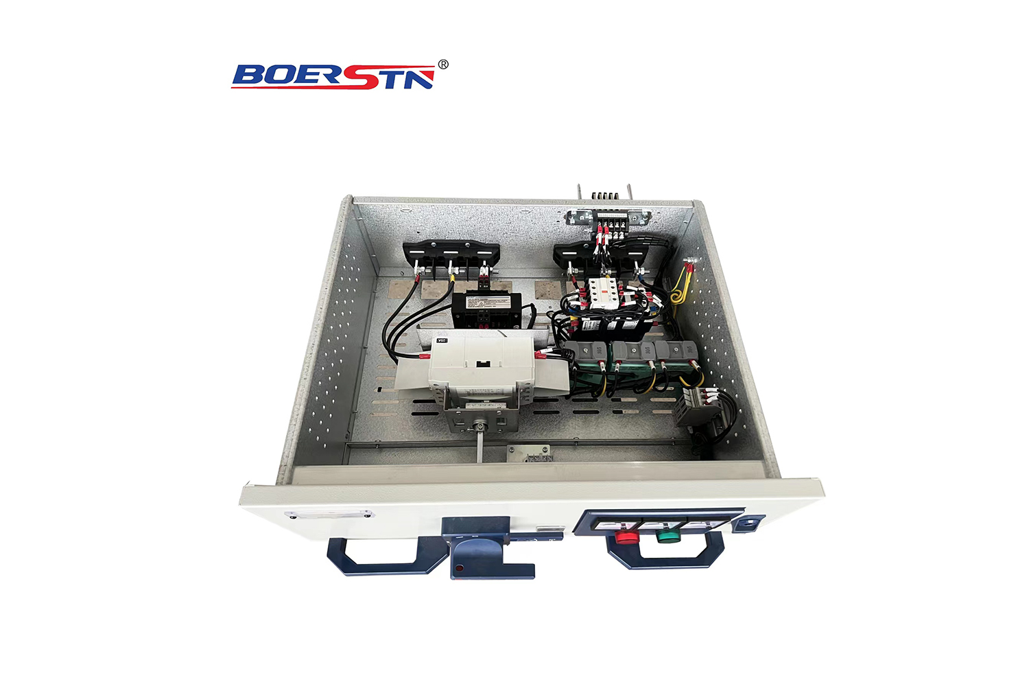
    ● Lubricant should be added when truck’s plug-in mechanism and contact is in short of or lack of lubricant.
    ● Clean the movable contact surface of switchgear (such as hinged shutter, interlocking mechanism,system levering mechanism and truck wheels), and apply lubricant.
    ● Observe maintenance instruction stipulated in this book.

  • Repair

    General Repair
    ● If any defect, commit repair as soon as possible.
    ● Clean the rust on steel plate and other elements with mechanical method (such as copper brush).
    ● Rub softly the edge of paint and clean greasy dirt. Apply anti-corrosion base paint as soon as possible, after the base paint is dry, apply finishing coat. The thickness of coat is approximately 60um. Appropriate compatible paint can be used.
    ● Brush off the white rust spot on zinc plated or chrome plated functional element. Clean rust spot with dry and clean cloth. After installation is finished, apply base paint as soon as possible, then the finish paint. The total thickness of coat is approximately 30um. Epoxy resin base paint and polyurethane finish paint is especially applicable.
    ● Removable and rotating element(such as rotating shaft and link lever) don't need any paint, but lubricant should be applied.

  • Replacement of Components
    When placing an order, the correct name, type, applicable current and voltage rating should be specified. Nameplate and technical instruction can be used as reference.

  • Warning

    Pay attention to this instruction and safety operation regulations.
    Dangerous voltage may cause shock and fire. Cut off the power before perform any work in the live area.
    ● Make sure the installation, operation and service must be processed by professional electrical engineers.
    ● Keep legal laws, operation criterion of local power department and relevant safety operation regulations.
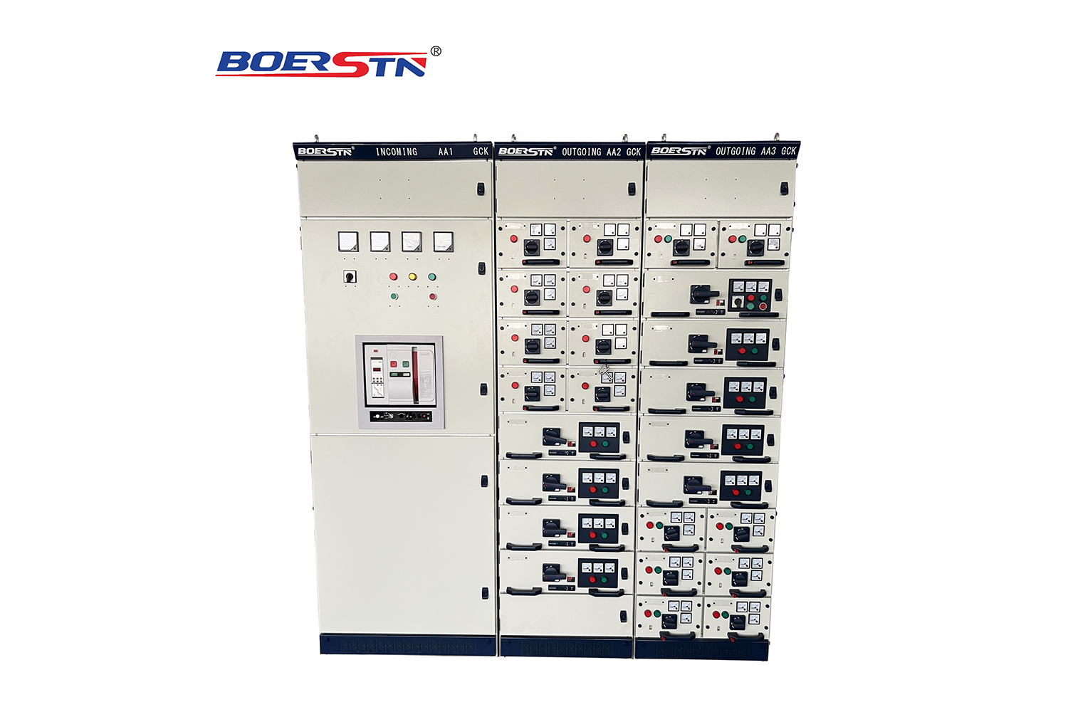
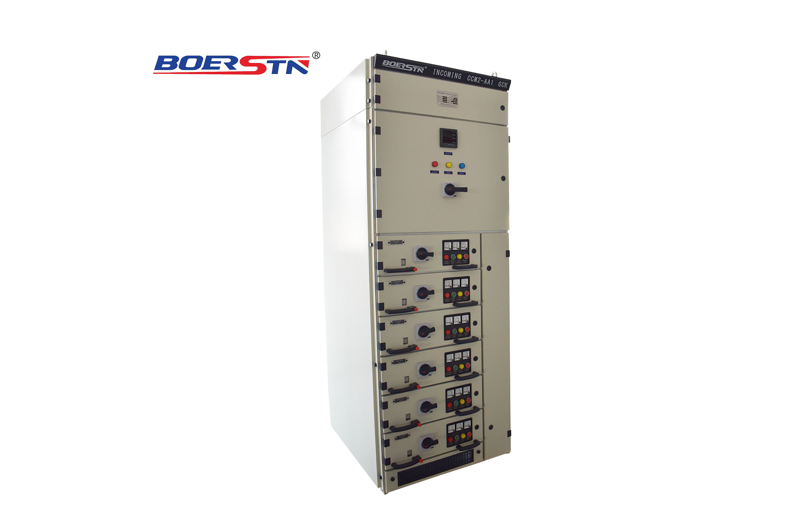
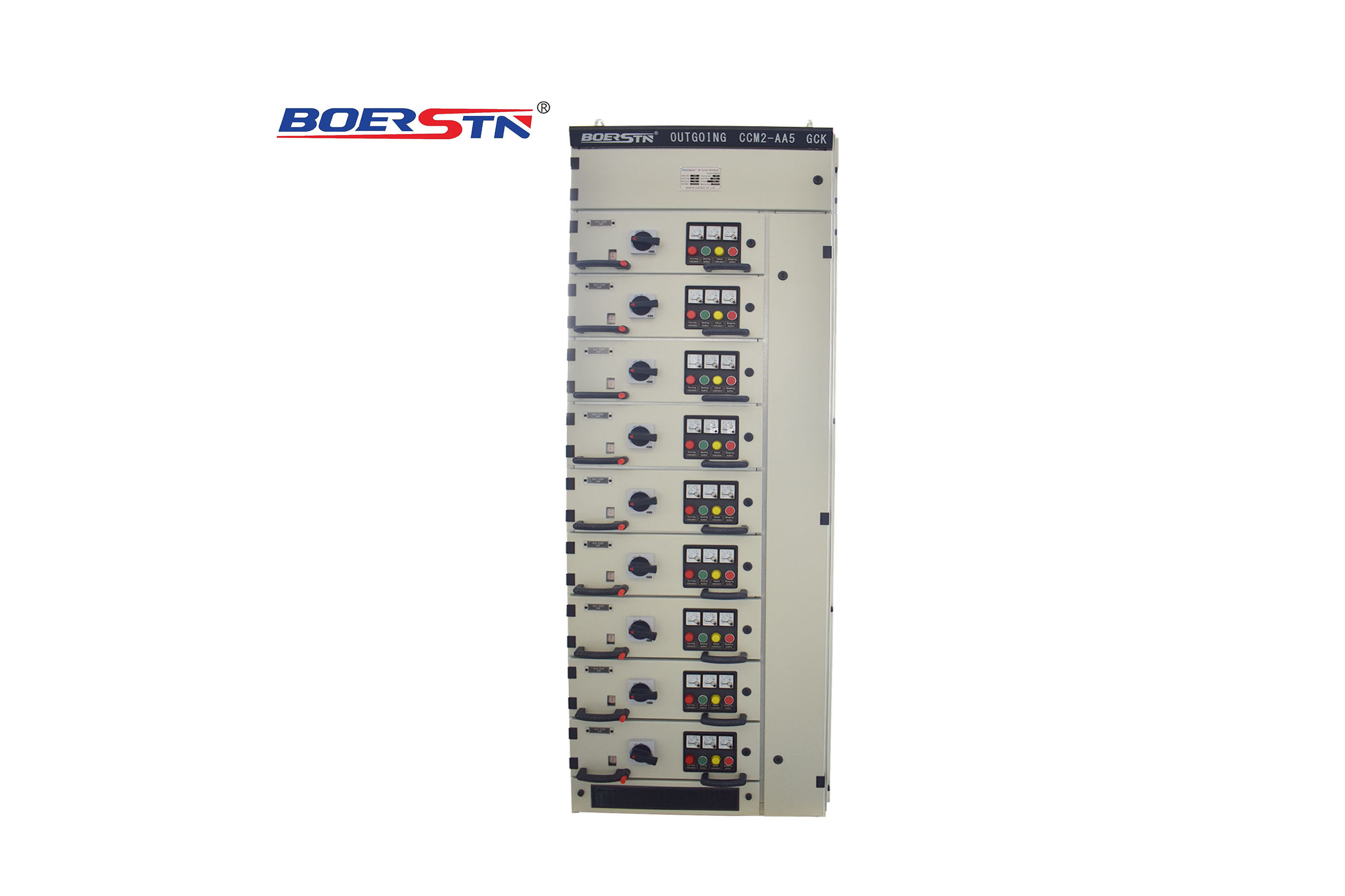
    ● Any activity related to GCK 、GCS、MNS switchgear should consult with this instruction.
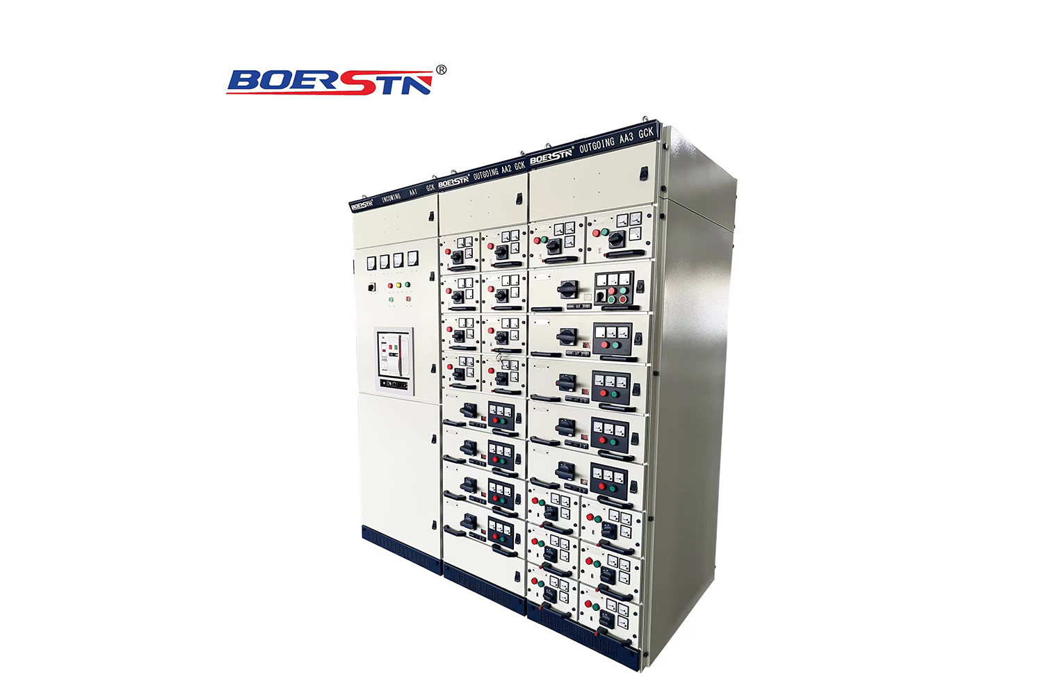
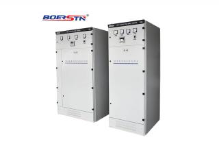
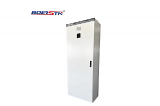
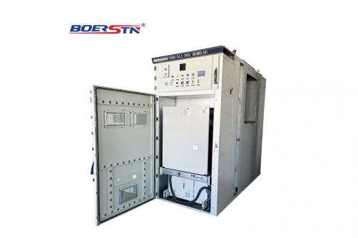
    ● The Low voltage switchgear is of the indoor distribution equipment, it must be installed in buildings applicable for electrical devices.
    ● Never exceed the rated technical data specified by switchgear nameplate.
    ● Make sure personnel responsible for installation, operation and service are easy to get this instruction.
    ● Operator should take correct and efficient resolution when any problem occurs.
    ● We are always glad to answer any relevant questions.

Transportation and storage

  • 1.Don’t tilt and shake violently
    2.Use the transport of angle plate in unpacking after lifting, the angle between two steel wire ropes should be less than 120°. If use forklift, rolling stick or crowbar are not allowed to directly on the device on the chassis
    3.If need to move it a little after installation, can move four corners on the underframe
    4. The inside electrical parts or accessories are not allowed to be disassembled

Installation schematic diagram (Figure 7)

Bus bridge Installation diagram (Figure 8)

Feedback form contact with us
Related Product
Low Voltage Withdrawable Switchgear GCK, GCS, MNS(SYN)
Service Conditions 1. Ambient temperature:-30℃ ~ +50℃,and measuring average RH within 24 hours ≤+50℃; 2. Altitude: Not exceed 20...
Low Voltage Fixed Switchgear GGD
Product description GGD type LV low voltage distribution cabinet is based on the higher charge of energy department  and the ...
Low Voltage APFC Capacitor Bank GGD
Product description Capacitance compensation is reactive power compensation or power factor compensation. The electric equipment o...
Low Voltage Fixed Electrical Power Distribution Board XL-21
Product description Cabinet front door installed ammeter ,voltmeter and the signal lamp, button, selector switch and other compone...
Product Catalog