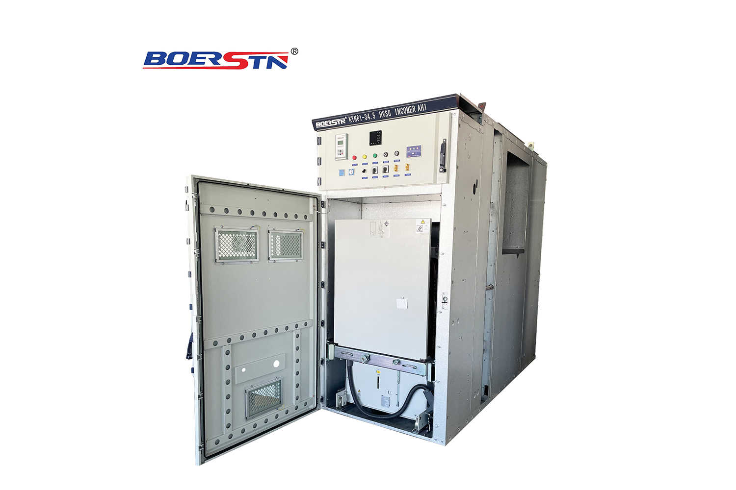
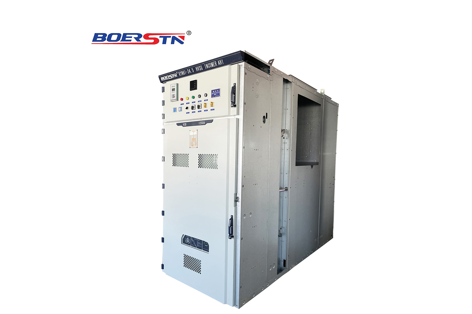
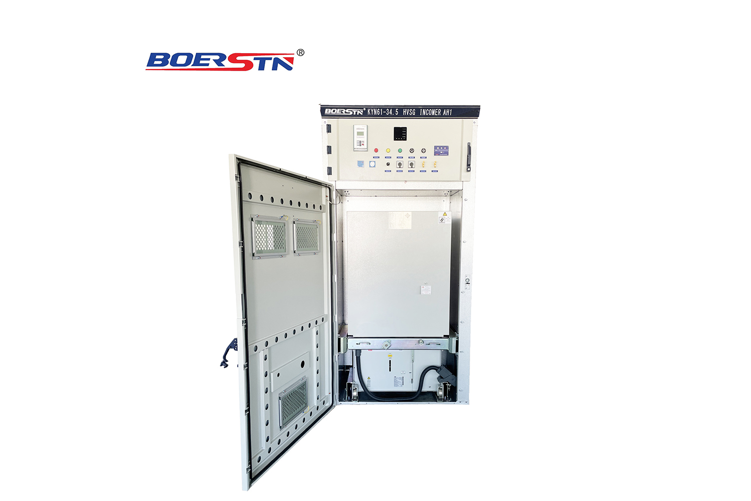
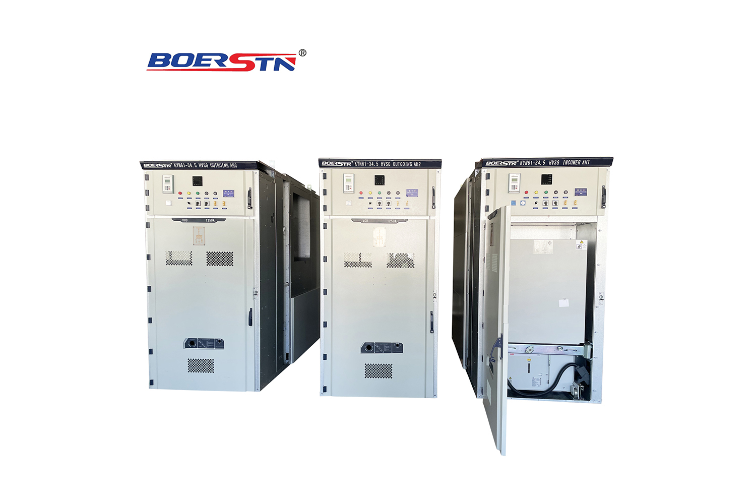
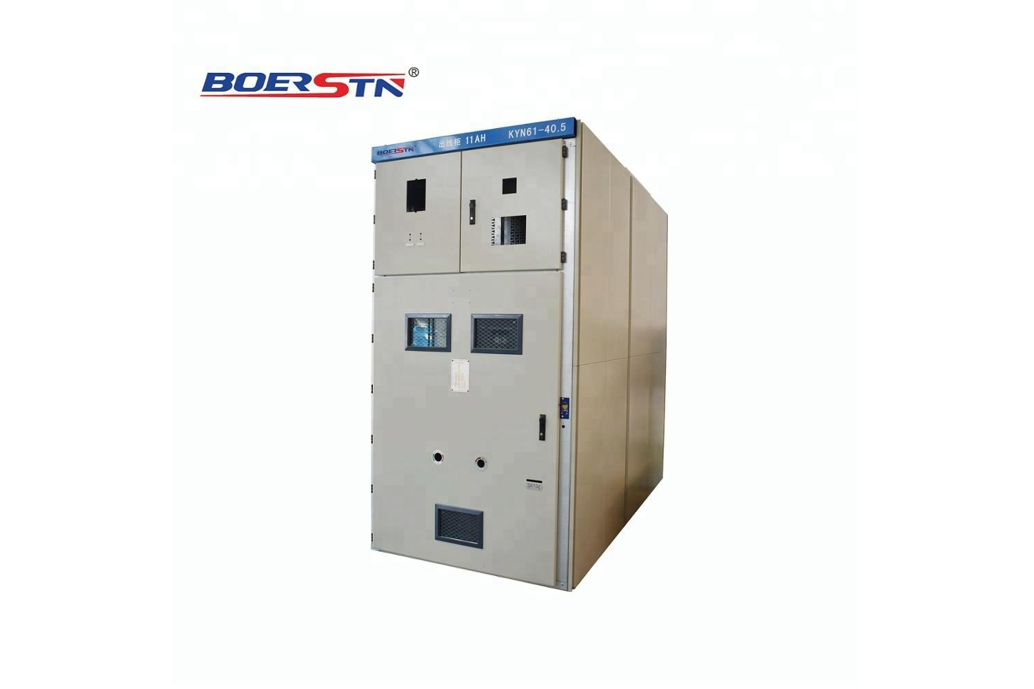
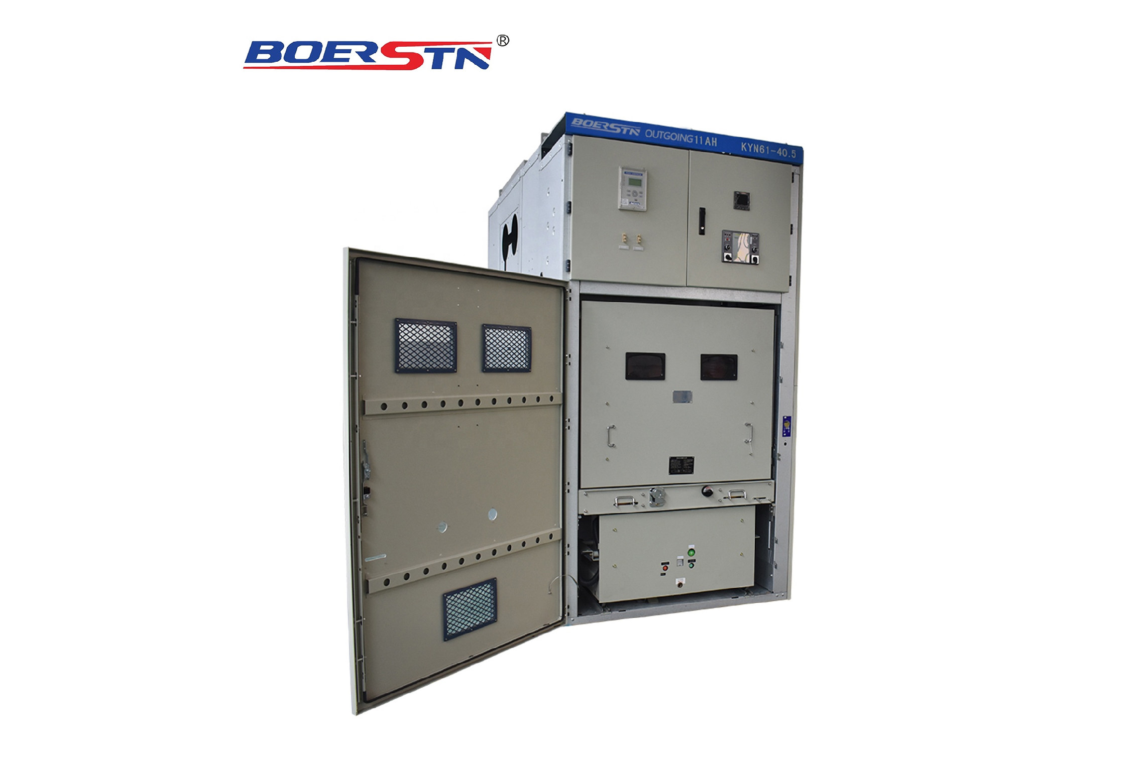
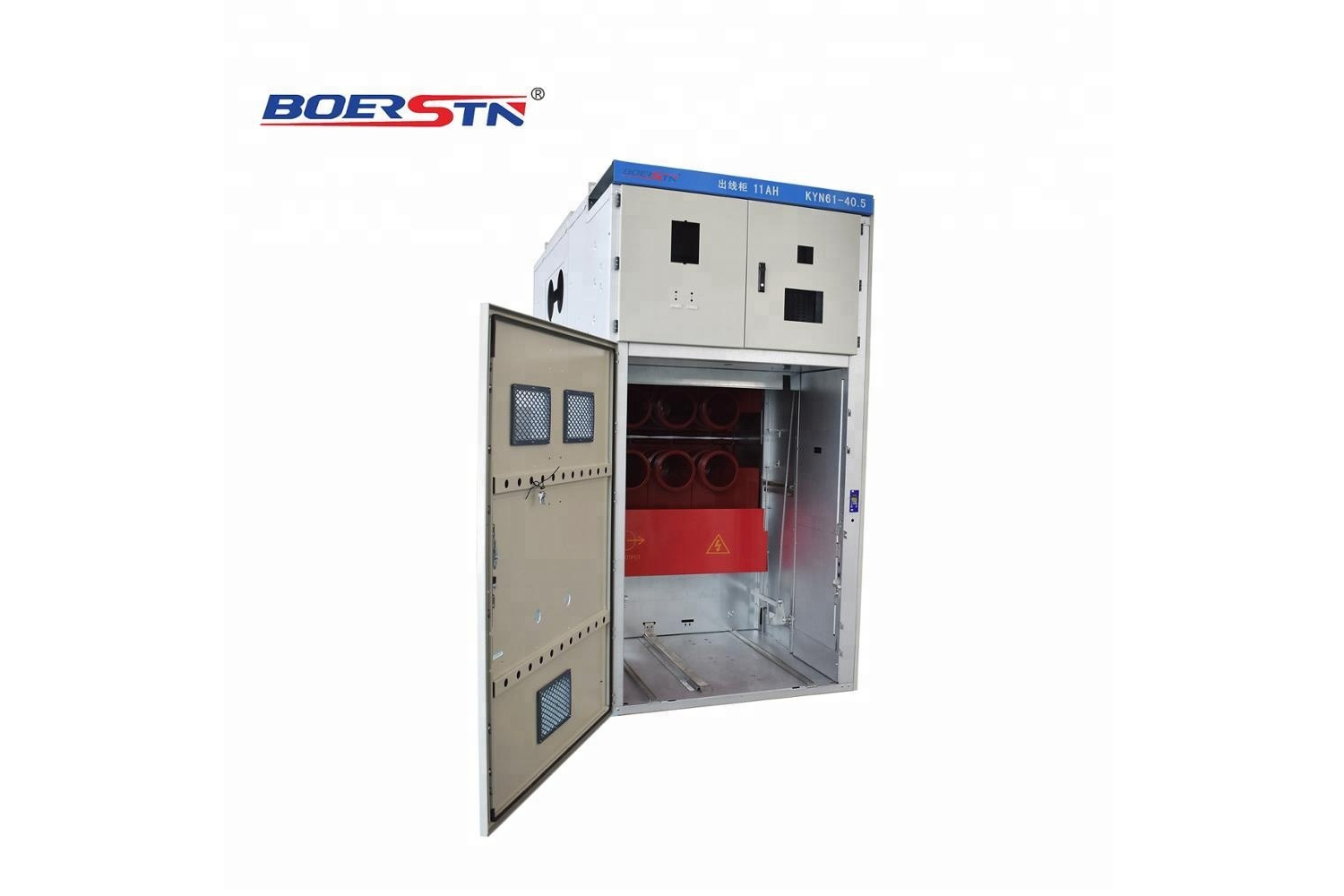
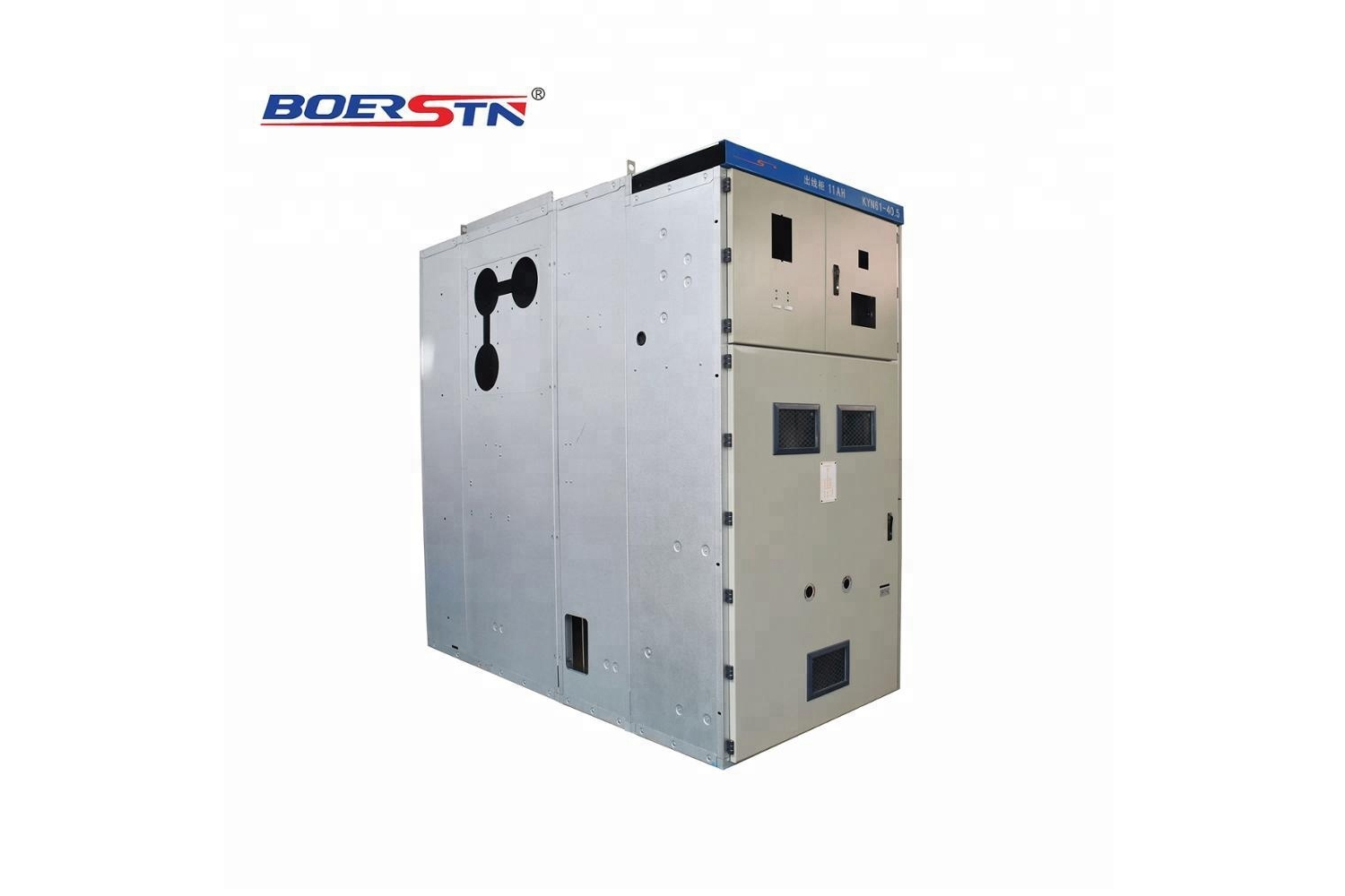
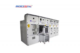
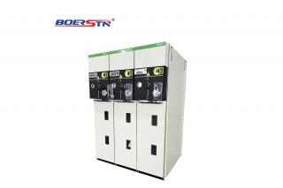
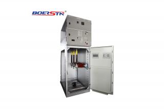
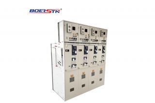
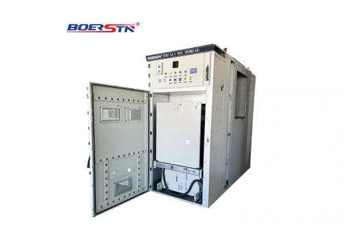
High Voltage Withdrawable Switchgear KYN61-40.5KV
KYN61 air-insulated metal-clad withdrawable switchgear (hereinafter as “switchgear”) is a necessary indoor power distribution equipment in 40.5 kV 3-phase AC 50/60Hz.It is mainly used to distribute electrical power in power station and substations of mine,industry and electrical power supply system.Also it is used in control, protection and monitoring etc for line circuit as well as frequently operation site. The switchgear meet the requirements of standard IEC62271-200 IEC62271-100 etc.
Share This Product:
  • product details
  • Switchgear Structure Characteristic
  • Switchgear Installation

Main characteristic

  • 1. Cabinet structure adopts assembly type, circuit breaker adopts handcart floor type structure;
    2. Fitted with completely new type of composite insulation of vacuum circuit breaker, and has good compatibility and replace simply characteristic;
    3. Handcart frame is provided with a screw nut propelling mechanism, which can be easily moved by the hand cart, and can prevent the damage of the pushing structure from the misoperation ;
    4. All operations can be carried out when the door closed;
    5. Main switch, trolley, interlock between switchgear door adopts the mandatory mechanical locking to meet "five protection" function;
    6. The space of cable room is ample, and can connect a plurality of cables;
    7. The quickly earth switch for grounding and line circuit short circuit;
    8. Shell protection class IP3X, when handcart room door opening , protection level IP2X; 9. Products comply with IEC62271-200 ,GB 3906-2006, DL/T 404-2007 and reference to the standard of international IEC 298.

Service Conditions

  • 1. Ambient temperature:-30℃ ~ +50℃, and measuring average RH within 24 hours ≤50℃;
    2. Altitude: Not exceed 2500m above sea level;
    3. Ambient humidity: Daily average RH ≤ 95%;
    Monthly average RH ≤ 90%
    4. Earthquake intensity: ≤ Degree 8;
    5. Water vapor pressure:Daily average RH ≤ 2.2kPa;
    Monthly average RH ≤ 1.8kPa;
    6. Ambient environment: no fire, explosion danger, serious pollution, chemical corrosion and severe vibration place

Technical Parameters

Vacuum Switchgear mainly technical parameters

No

Description

Unit

Data

1

Maximum system voltage

kV

40.5

2

Rated Voltage

kV

30、33、36

3

Rated Current

A

630 ,1250 ,1600,2000,2500,3150,4000

4

Rated Frequency

Hz

50/60

5

Rated short-time withstand current

kA

25、31.5、40

6

Rated Peak withstand current

kA

50、63

7

Rated power frequency withstand voltage

kV

85/1min

8

Rated impulse lightning withstand voltage

kV

185

9

Rated short circuit duration

s

4

10

Protection level


IP4X


Vacuum Circuit Breaker Main Technical Parameters

No

Description

Unit

ZN85  Data

1

Rated Voltage

kV

40.5

2

Rated Current

A

630 ,1250 ,1600,2000,2500,3150

3

Rated Frequency

Hz

50/60

4

Rated short-time withstand current

kA

25、31.5、40

5

Rated short circuit break current

kA

25、31.5、40

6

Rated Peak withstand current

kA

50、63

7

Rated power frequency withstand voltage

kV

85/1min

8

Rated impulse lightning withstand voltage

kV

185

9

Rated short circuit duration

s

4

10

Open time

ms

30≤t≤60

11

Close time

ms

50≤t≤100

12

Rated short circuit break current numbers


2

13

Mechanical Endurance

Times

10000


Spring operating mechanical main technical parameters

No

Description

Unit

Data

1

Rated Voltage

Open coil

V

DC220/110   AC220/110

Close coil

2

Rated operate current

Open coil

A

0.96(220 V) 1.05(110V)

Close coil

3

Spring charge motor

W

230

4

Spring charge motor rated voltage

V

DC220/110 AC220/110

5

Spring charge time

S

≤12

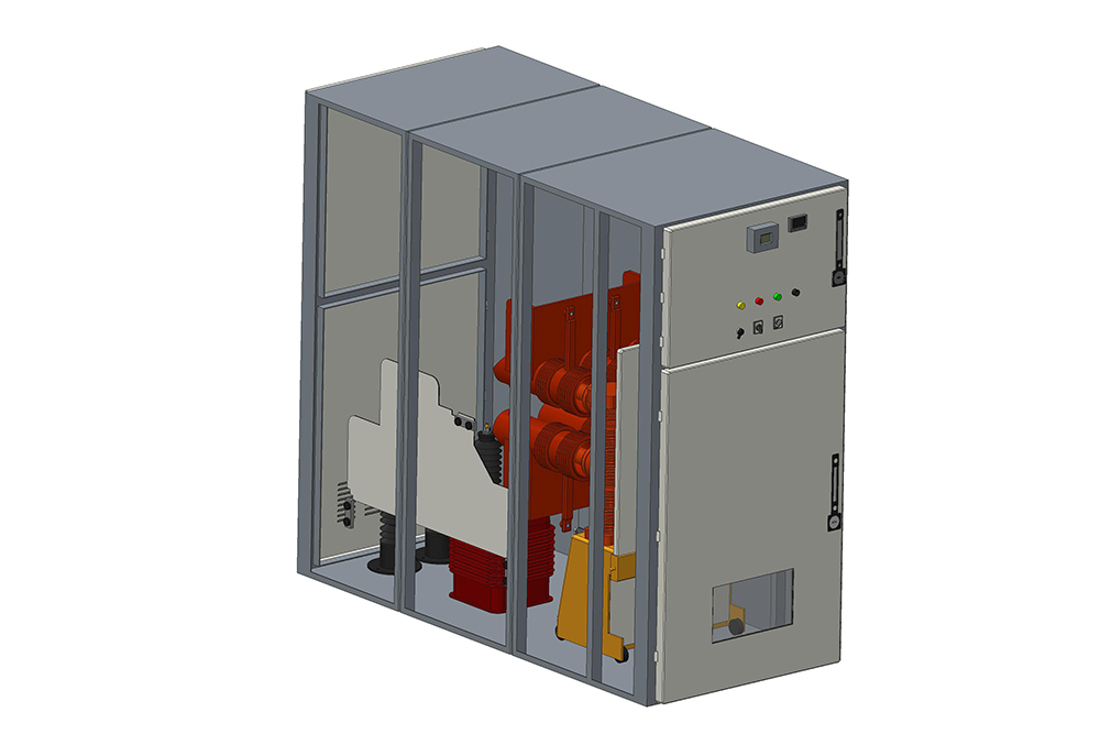
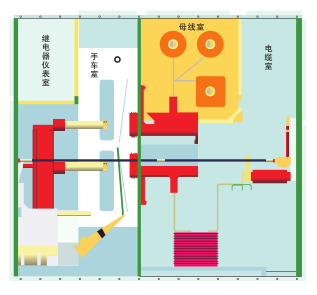
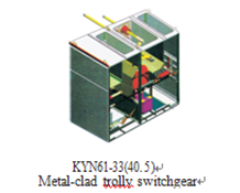
  • The switchgear is designed in accordance with the requirement of metal-clad switchgear under the standard IEC62271-200, IEC298. The switchgear is composed of the cabinet body and center located withdrawable parts. The cabinet body of the structure is assembly type, and assembled by bolting ,and adopting the metal board to divide switchgear into circuit breaker chamber, the main bus chamber, cable chamber and the relay instruments chamber .The protective level of the enclosure is IP3X , while the protective level is IP2X between the compartments ,and all the metal structure parts are reliably grounded, and the main loop system of each compartments has independent exhaust pressure release channel.

  • 1. Enclosure and partition

    The Enclosure and partition plate of the switchgear is made of cold rolled steel plate after being processed by a numerical control machine and bolting by benting . As a result, the assembled switchgear can ensure the unity of the structural dimensions. Switchgear is divided into circuit breaker chamber, the main bus chamber, cable chamber and the relay instruments chamber, each parts to be separated by a grounded metal partition.

  • 2. Handcart

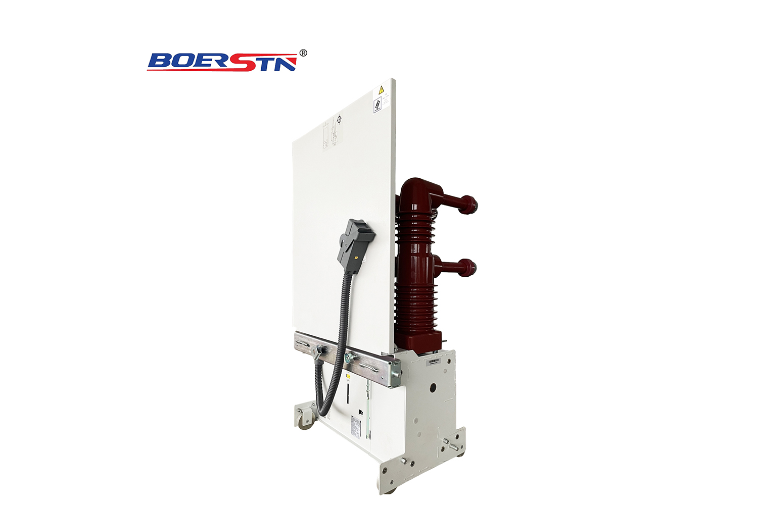
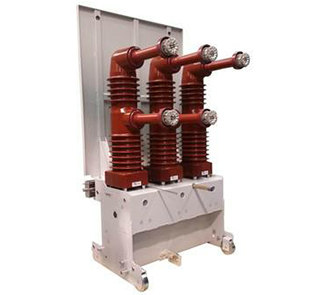
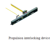
    According to handcart using purpose , it can be divided into the circuit breaker handcart , the voltage transformer handcart , measuring handcart isolation handcart , etc., all kinds of handcart outline dimension is same , the using purpose of handcart with interchangeability. Handcart has test /isolation position and service position, each position is equipped with interlocking devices to ensure that the handcart can not move when it is in above test /isolation position and service position.

  • 3.Circuit Breaker Compartment

    The circuit breaker compartment is fitted with the necessary guide rails to accommodate the withdrawable part,which can be moved between the service position and the test position. The isolation valve is automatically opened or closed to ensure staff not touch the charged body.The withdrawable part can be operated when the door of panel closed.through the observation window to see the handcart in the cabinet position , at the same time to see any function signs on the handcart.

  • 4.Bus Compartment

    Main bus are laid in sections from panel to panel by branch small bus and fix contacts box to fix .Across side board of the adjacent cabinet with bus bushing to fix. All buses adopt composite insulation.

  • 5. Cable Compartment

    Cable compartment can be installed PT, earthing switch, lightning arrester and a plurality of cables.

  • 6. Relay Compartment

    Relay compartment inner board and panels can be installed to control, protection components, measurement, display instruments, live monitoring indicators etc secondary components.

  • 7. Interlocks device

    ●Switchgear has reliable interlock device to ensure the safety of operators and equipment:
    ●When the earthing switch in the off position, the truck can move from the test / disconnected position to the service position and the back door can not be opened to prevent accessing into live space.
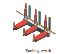
    ●When the truck pulled completely out of cabinet outside or truck in the test/isolation position in the cabinet and the earthing switch interlocking can unlock , the earthing switch can close operation; The truck is in the working position, earthing switch can not be closed to prevent the earthing switch mal-closing with the electrification and prevent the earthing switch in the closed position when the truck moved to the service position.
    ●The circuit breaker truck in the test / disconnected position or working position, we can operate circuit breaker ; after circuit breaker closed ,the truck can not move to prevent mal- pushing and mal-pulling circuit breaker under charged load
    ●The electric interlocking can be installed between cabinets .

  • 8.Earthing device

    In the cable chamber, alone with Φ6× 50mm2 grounding bus, which can run through the adjacent cabinets, and good contact with cabinets

Switchgear outline dimension

Outline dimension (W×D×H)mm:

Switchgear structure sketch

A  Relay instruments chamber

B Bus chamber

1400×2800×2600

C  Circuit beaker chamber

D Cabl e chamber

1200×2800×2400

1200×3000×2600

Switchgear installation

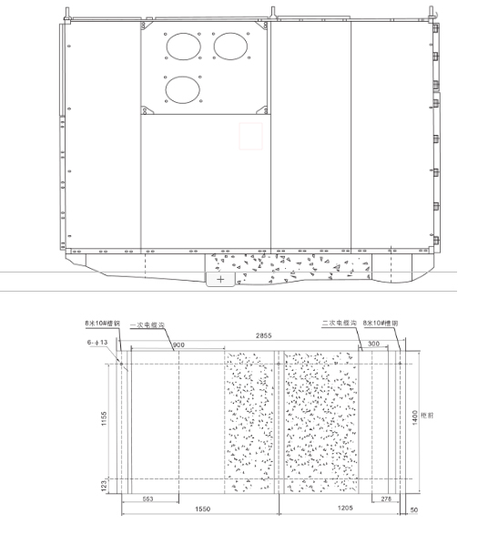
  • 1.Height of electrical room: ≥4500mm;
    2. Distance from cabinets back to wall: ≥1500mm;
    3. Basic frame of flatness: ≤1 mm/m2;
    4.Based on embedded channel higher ground shall not exceed 3mm;
    5. Available bolts or welding can be fixed on the foundation;
    6. Switchgear weight about :1800Kg;
    7. Switchgear operating corridor width (single row): ≥3000mm,double row (face to face ) ≥4000mm.

Schematic diagram of switchgear installation foundation

Feedback form contact with us
Related Product
High Voltage Withdrawable Switchgear KYN28A-12/24KV
Product description KYN28A air-insulated metal-clad withdrawable switchgear (hereinafter as “switchgear”) is a necessary indoor po...
High Voltage Fixed SF6 Ring Main Unit(RMU) BRSM6-12/24/40.5KV
Product description BRSM6 series SF6 ring main unit is SF6 switch as the main switch and the entire unit adopts air insulated, sui...
(NEW)High Voltage Fixed SF6 Ring Main Unit(RMU) HXGN15-12/24/40.5KV
Convenient Installation Its small volume & light weight make user to install & delivery it more conveniently and easy . It...
High Voltage SF6 Gas Insulated Switchgear(GIS) BRM6-12/24/40.5KV
Product description BRM6 series gas insulated compact type metal enclosed switchgear (hereinafter GIS ) is our introducing of fore...
Product Catalog