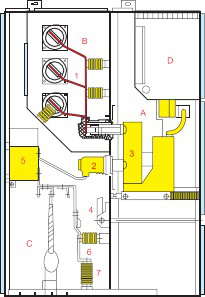
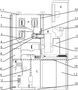
A.Circuit breaker chamber
B.Bus chamber
C.Cable chamber
D.Relay instruments chamber
1.Bus bar
2.Fix contact box
3.Circuit breaker
4.Earth switch
5.Current transformer
6.Capacitive voltage divider
7.Lightning arrester
1.Enclosure
2.Branch small bus
3.Bus bushing
4.Main bus
5.Fix contact device
6.Fix contact box
7.CT
8.Earth switch
9.Cable
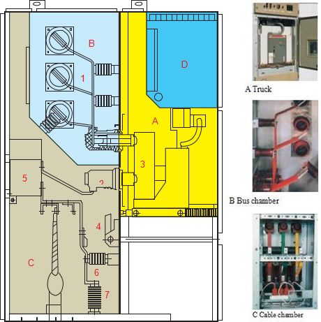
A. Bus chamber
B. Circuit breaker truck chamber
C. Cable chamber
D. Relay instruments chamber
1.1 pressure relief device
1.2 Control small wire slot
14. Secondary plug
15. Circuit truck
16. Heater
10.Lightning arrester
11.Grounding main bus
12.Loading and unloading type partition
13.partition(valve)
17. Draw out type horizontal partition
11.Grounding main bus
18. Earthing switch operation mechanism
12.Loading and unloading type partition
19.Bottom plate
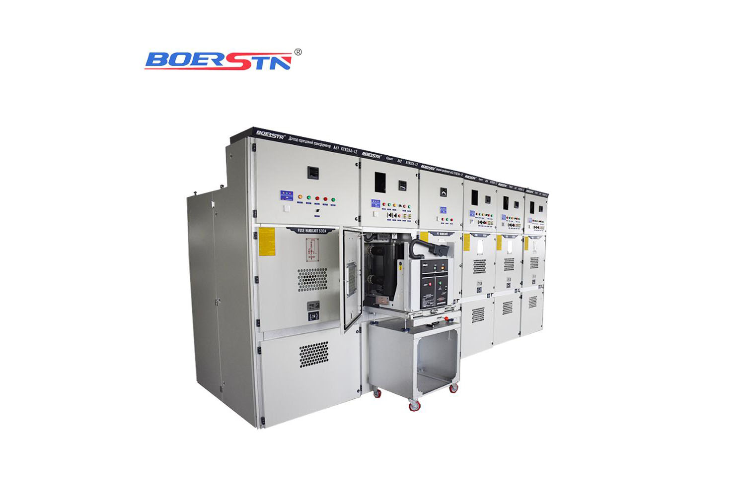
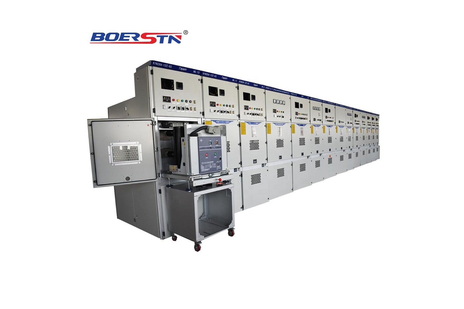
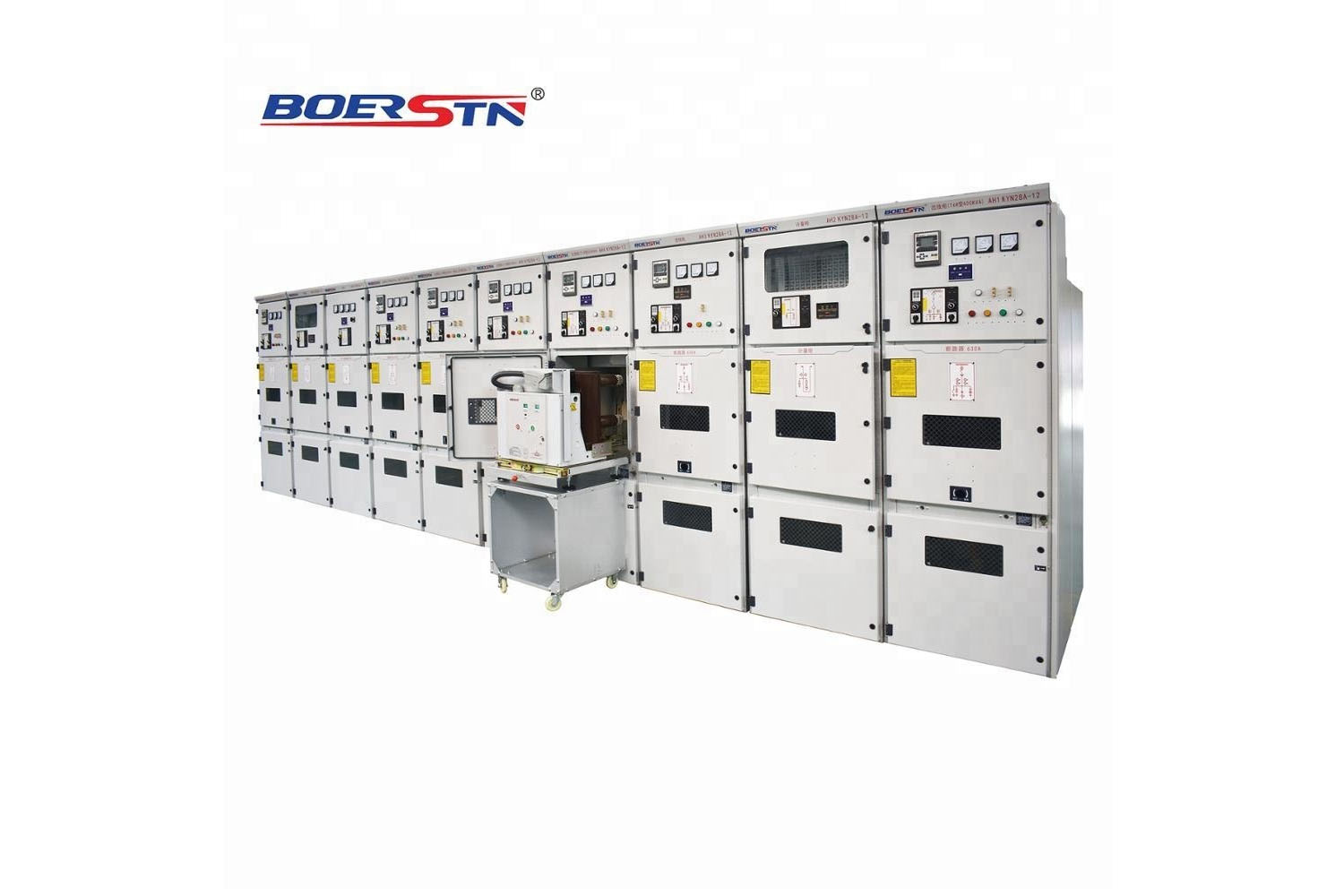
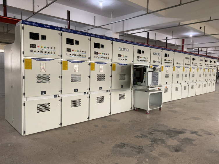
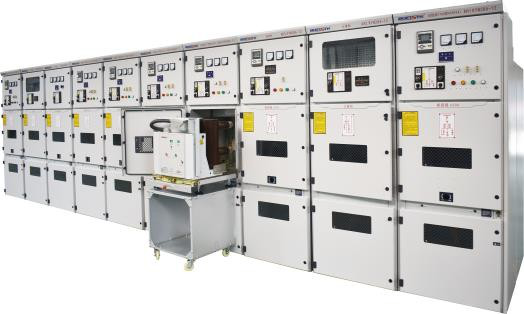
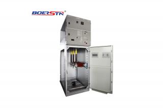
The switchgear is composed of a fixed body and a withdrawable part (the handcart) (switchgear structure shown in Figure 2), switchgear enclosure and function modules are using aluminum-clad galvanized steel sheet to bolt together . The protection level of the switchgear enclosure is IP3X, while the protection level is IP2X between the partition boards and circuit breaker door .
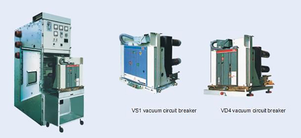
KYN28A-12/15/24 type switchgear could match VS1 type vacuum circuit breaker handcart and VD4 vacuum circuit breaker handcart and ABB manufactured VC series vacuum contactor, switchgear can be installed to back-to-back arrangement. The switchgear installation and commissioning can be operated in the front, so the switchgear can be mounted against the wall, the biggest advantage of againsting the wall can save area, and can also off wall installation, namely double maintenance type, the two of internal structure layout is not uniform, it has the advantages of convenient maintenance.
Enclosure and partition
-
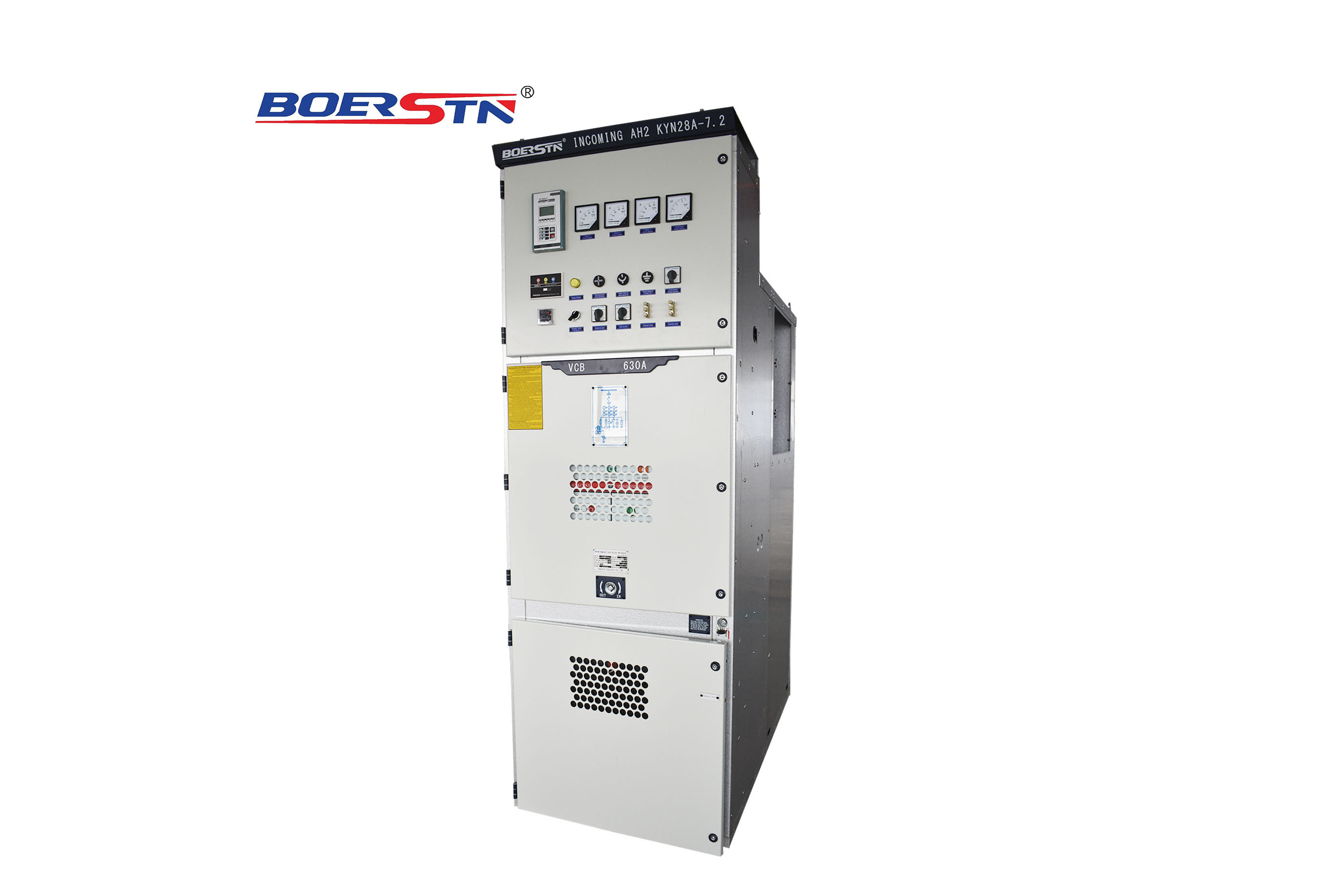
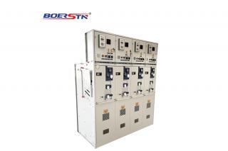
The enclosure and partition of the switchgear is made of top quality imported aluminum-clad galvanized steel sheet through multiple edge-folding processing with CNC machine tool. The assembled switchgear could keep uniform in dimension, and it has high corrosion resistance and oxidation resistance and higher mechanical strength than equal steel sheet. The switchgear is divided to handcart chamber ( circuit breaker chamber ), bus chamber , cable chamber and relay instrument chamber ( LV chamber ) each unit enclosure are independently earthing.
Cabinet overview
-
The enclosure and partition of the switchgear is made of top quality imported aluminum-clad galvanized steel sheet or steel sheet through multiple edge-folding processing with CNC machine tool. The assembled switchgear could keep uniform in dimension. Aluminum-clad galvanized steel sheet has a strong corrosion resistance and oxidation resistance, and higher mechanical strength than qual steel sheet. The switchgear is divided to handcart chamber ( circuit breaker chamber ), bus chamber , cable chamber and relay instrument chamber ( LV chamber ) each unit enclosure are independently earthing .The door of switchgear are using electrostatic spraying to make the surface with the advantage of anti impact, corrosion resistance, beautiful appearance (color can be set by the user) etc..
|
|
Description
|
12(15)kV
|
24kV
|
|
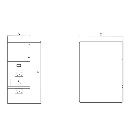
Height(B)
|
Cabinet
|
2300mm
|
2430mm
|
|
Width(A)
|
Branch bus current less than 1600A, short circuit break current at 31.5kA
|
800mm
|
1000mm
|
|
Branch bus current more than 1600A
|
1000mm
|
1000mm
|
|
Depth(C)
|
Cabinet
|
1500mm
|
1860mm
|
|
Weight(kg)
|
800~1200
|
Switchgear outline dimension diagram
-
A Handcart
The truck frame series adopts thin steel plate by CNC machine after processing by riveting, welding to make it. According to the use of handcart, which can be divided into circuit breaker handcart, voltage transformer handcart, isolator handcart, metering handcart, etc.. The handcart with same purpose could convenient to exchange.The handcart has the isolation position, the test position and the work position in the cabinet, each position is provided with the positioning device, so as to ensure that the handcart can not move freely when the position is in above , while moving handcart, it must be unlocked
-
B Bus room
The bus bar is led from one switchgear to another switchgear by branch bus bar and static contact box to fix. The flat branch bus bar is connected with the static contact box and main bus bar by bolts, and it does not need any other wire clip or insulator connection. When the user and the special needs of the project, the busbar connection bolts can be insulated and end cap packaging. When the bus across clapboard of the switchgear by bus bushing to fix. If an internal fault arc occurs, the accident can be limited to extend to the adjacent panel and the mechanical strength of the busbar can be ensured.
-
C Cable room
An cable room could install current transformer, grounding switch, arrester and cable, and at the bottom of the preparation of slotted removable aluminum plate to ensure the construction site conveniently.
-
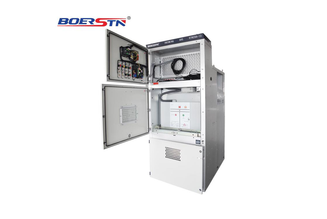
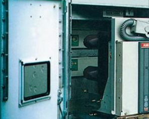
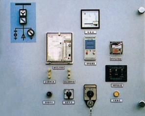
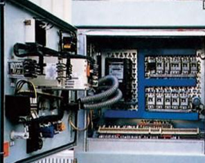
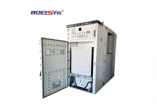
D relay instrument room Instrument room door open, instrument room inner view
-
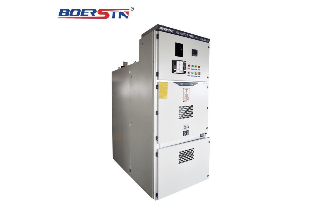
D relay instrument room Instrument room door close, instrument room front view
-
Lock structure
-
-
-
-
-
D relay instrument room
The relay instrument room is used to install all kinds of relays, instruments, signal indication, operation switch and other components. In addition, according to user requirements for adding a small bus room in the top of the instrument room , and can lay of sixteen loops controlling small bus .
-
Pressure relief device
A pressure relief device in the upper handcart rooms, bus room and cable room, when the circuit breaker or main bus, cable indoor occur internal fault arc ,with the appearance of arc, internal pressure of switchgear rises, and reaches a certain pressure, the pressure relief device at the top of the metal plate will be opened automatically, and release the pressure and excretion of gas to ensure the safety of operators and switchgear
-
Lock structure
Connection between the door and the cabinet with lock structure, and with the lifting mechanism to make it more convenient for opening the door, when medium door is in the closed state, which is connected with a strength of the cabinet body, strengthens the ability to effectively combat internal arcing fault.
Avoid misoperation interlocking device
-
The switchgear has reliable interlock device, which provides reliable safety and protection for operators and equipment , its function as follow:
1 When the grounding switch is in open position, the handcart can move from the test position to service position.
2.The handcart of the circuit breaker has been fully engaged in the test or service position before operation.
3.Handcart is in the service position, the secondary plug is locked and can not be removed.
4.The grounding switch is closed, the handcart cannot from the test position move to service position .
5.Grounding switch can only be operated when the handcart is in the test position or isolated position. The switchgear can be equipped with an electromagnet locking mechanism in the grounding switch operating mechanism to improve the reliability to prevent high voltage charged and misoperation grounding switch. Its order can be according to the user's needs.
Secondary plug and handcart position interlock
-
The secondary wires of the switchgear is connected with the secondary of the handcart through the manual secondary plug. The movable contact of the secondary plug is connected by the handcart and a nylon corrugated telescopic pipe, and the secondary static contact seat is arranged on the upper right side of the handcart compartment of the switchgear. Handcart is only in the test position and then can plug and remove secondary plug. When the handcart is in the service position, the secondary plug is locked and can not be removed ,because of the interlocking mechanism.
Grounding device
-
In a separate cable room install 8 x 40mm grounding bus bar, this row can run through the adjacent cabinet and good contact with cabinet, this ground row directly grounding for components using, at the same time ,as the whole cabinet with aluminum-clad galvanized steel sheet combining together, so that the entire cabinet are in good grounding state to ensure the safety operator touching cabinet .
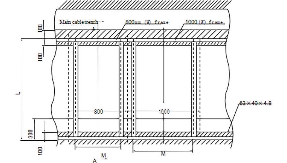
hematic diagram of switchgear installation
-
|
Width (mm)
|
Depth
|
M(mm)
|
L (mm)
|
|
800
|
1500 cable
|
630
|
1450
|
|
1660 overhead
|
1610
|
|
1000
|
1500 cable
|
830
|
1450
|
|
1660 overhead
|
1610
|
Schematic diagram of switchgear installation foundation
|
Width (mm)
|
Depth
|
L1(mm)
|
L2 (mm)
|
|
800
|
1500 cable
|
530
|
630
|
|
1660 overhead
|
|
1000
|
1500 cable
|
730
|
830
|
|
1660 overhead
|
Switchgear installation
-
1.Height of electrical room: ≥4500mm;
2. Distance from cabinets back to wall: ≥1500mm;
3. Basic frame of flatness: ≤1 mm/m2;
4.Based on embedded channel higher ground shall not exceed 3mm;
5. Available bolts or welding can be fixed on the foundation;
6. Switchgear weight about :1800Kg;
7. Switchgear operating corridor width (single row): ≥3000mm,double row (face to face ) ≥4000mm.
Schematic diagram of switchgear installation foundation
(I)De-Energising operation steps
1.The current standard operating conditions: The door must be in the closed position; meaning the circuit breaker is in the working position, the earth switch is in the
open position)
2.Circuit Breaker Opening, rotate the circuit breaker operating handle counter-clockwise①,until the circuit breaker hand trolley backing is set to test position②. (At this state, rail interlock is released, this will allow for the next step operation to be carried out successfully).
3.Firstly, make sure that the incomer vacuum circuit breaker is de-energised at the port cable , and then press operating shaft baffle③; to rotate earth switch operation handle at clockwise ④ until the earth switch in the closing state ⑤ (In this state ,the back door interlock is released, it will allow the next operation and step to be carried out).
4.Open front door and back door
(II)Energizing operation steps
(The current standard condition: all of door completely open, the circuit breaker in the testing position, the earth switch is in the close position)
1.Close front door①and back door②( it is necessary to close back door before pressing shaft baffle, and then operate earth switch)
2.Rotating the earth switch handle counter-clockwise③, until the earth switch is in the opening state ④. (In this state, back door is locked, which cannot open)
3.Rotating the circuit breaker operating handle clockwise⑤ ,this allows the circuit breaker trolley to move into working position ⑥
(III)HV switchgear "Five Anti" interlock operating requirements:
1.To prevent accidental closing and opening of circuit breaker-
The circuit breaker hand trolley must be in working position or test position; The circuit breaker can be carried out opening and closing operation.
2.To prevent moving circuit breaker hand trolley under load –the circuit breaker is in the opening, the circuit breaker hand trolley can be pulled or pushed into the operating position.
3.To prevent closing ground knife with charged - the circuit breaker hand trolley must be in the test position, ground knife can be carried out closing operation.
4.To prevent power transmission with ground knife - the ground knife must be in the
opening position, the circuit breaker hand trolley can be pushed into the work position to carry out closing operation.
5. to prevent mistakenly charged interval - the circuit breaker must be in the test position, grounding knife is in the closing state ,and then to open the back door; If the switchgear is no earth switch ,this kind of switchgear must be in high-pressure power failure (open back door electromagnetic lock), to open the back door .
(IV)Operation for taking the handcart out the switchgear:
1.When pulling out the VCB handcart (handcart of PT, isolation and fuse) from the switchgear, firstly all steps of blackout operation should be completed.
2.When making the earthing blade, the operating valve should be opened firstly in order to the close the earthing blade by using operating handle (in clockwise direction), then draw out the operating hand and confirm the earthing blade is in the status of making.(if you needn’t to close the earthing blade, this operation should not be done.)
3.Open the front door of switchgear (door of VCB compartment) and draw out the secondary plug of handcart.
4.Put the transfer trolley and lock it in the specified position in front of switchgear; the left/right handle of handcart should be pulled inward to the Ⅱ position at same time and take it out to the transfer trolley, then the left/right handle should be pulled outward to the Ⅰ position at same time so as to be reliably locked with key hole of transfer trolley.
5.Check the protection valve of upper and lower fixed contact of switchgear in automatic closed position and then close the front door of switchgear (door of VCB compartment)
(V)Blackout overhauling of HV cable compartment:
1.All steps of blackout should be completed.
2.Open the operating valve of earthing blade, close the earthing blade by using the operating handle (in clockwise direction), and then draw out the operating handle to confirm the earthing blade is in the status of making. At this time, outgoing side of cable is in safety ground state.
3.Open the back door of switchgear(cable compartment), detect and confirm all conductive parts in the cable compartment is completely in power cut condition by using HV electroscope, Maintenance personnel can enter into the HV cable compartment for work.
(VI)Blackout overhauling of HV busbar compartment:
1.All steps of blackout should be completed.
2.Confirm VCB handcart of the incomer switchgear and sectional switchgear have been in the test position or isolated position outside of the switchgear, and ensure the incoming cable or busbar has been in the power outage state.
3.Open the rear cover plate of HV busbar compartment or upper plate, detect and confirm all conductive parts in the busbar compartment is completely in no-voltage condition by using HV electroscope, Maintenance personnel can enter into the
HV busbar compartment for work.
(VII). Notes
1.The circuit breaker cannot withdraw to the test position, and cannot press operating shaft baffle
2.The back door is not closed, and cannot press operating shaft baffle.
3.The operating shaft baffle cannot press, you cannot rotate the earth switch operating handle.
4. grounding switch is closed, the circuit breaker cannot shake into.
5. grounding switch is opening, the back door cannot be opened, if the back door opened, it cannot be closed.
6.Please confirm that switchgears and handcart are in normal status, after each procedure is finished .If meeting any hinders during operation, do not operate forcibly. Firstly should check whether the operation is ok or not. Check and resolve other hinders, then keep on operating.
7.If there are many special requirements for control and operation, should control and operate according to design requirements.
8.Power transmission sequence: Metering or busbar PT panel ~ Incomer ~Outgoing; Blackout sequence: Outgoing ~ Incomer ~Metering or busbar PT panel.
9.While PT handcarts, isolation handcarts, VCB handcarts are moving into the switchgear or leaving out switchgear, the operation of earthing blade can be canceled.
10.The manual close/open button as well as the manual charge device in the VCB, only can be used when debugging or overhauling.
11.When the switchgear are running, client should inspect and record the operation status of switchgear frequently. If finding any usual phenomena (such as abnormal heating or usual sounds of components), it should cut off the power in time and overhaul.
Complete set to provide the following documents
1 Product certificate;
2Product packing list;
3Product factory test report;
4 Product manual instruction;
5 Equipment list;
6.Secondary wiring diagram;
7. The products are supplied according to the catalog and equipment list;