(NEW)High Voltage Fixed SF6 Ring Main Unit(RMU) HXGN15-12/24/40.5KV
(NEW)HXGN15 series is composed by standard finished function units from the factory, it adopts advantaged FLN36 load break switch (LBS), use SF6 gas with superior performance as arcing insulating medium.It is small ,compact and convenient installation, safety, stable working. It is widely used in 7.2~40.5kV electric power distribution system. The switchgear meet the requirements of standard IEC62271-200,IEC62271-100 etc.
Share This Product:
  • product details
  • Switchgear Structure Characteristic
  • SWITCHGEAR INSTALLATION

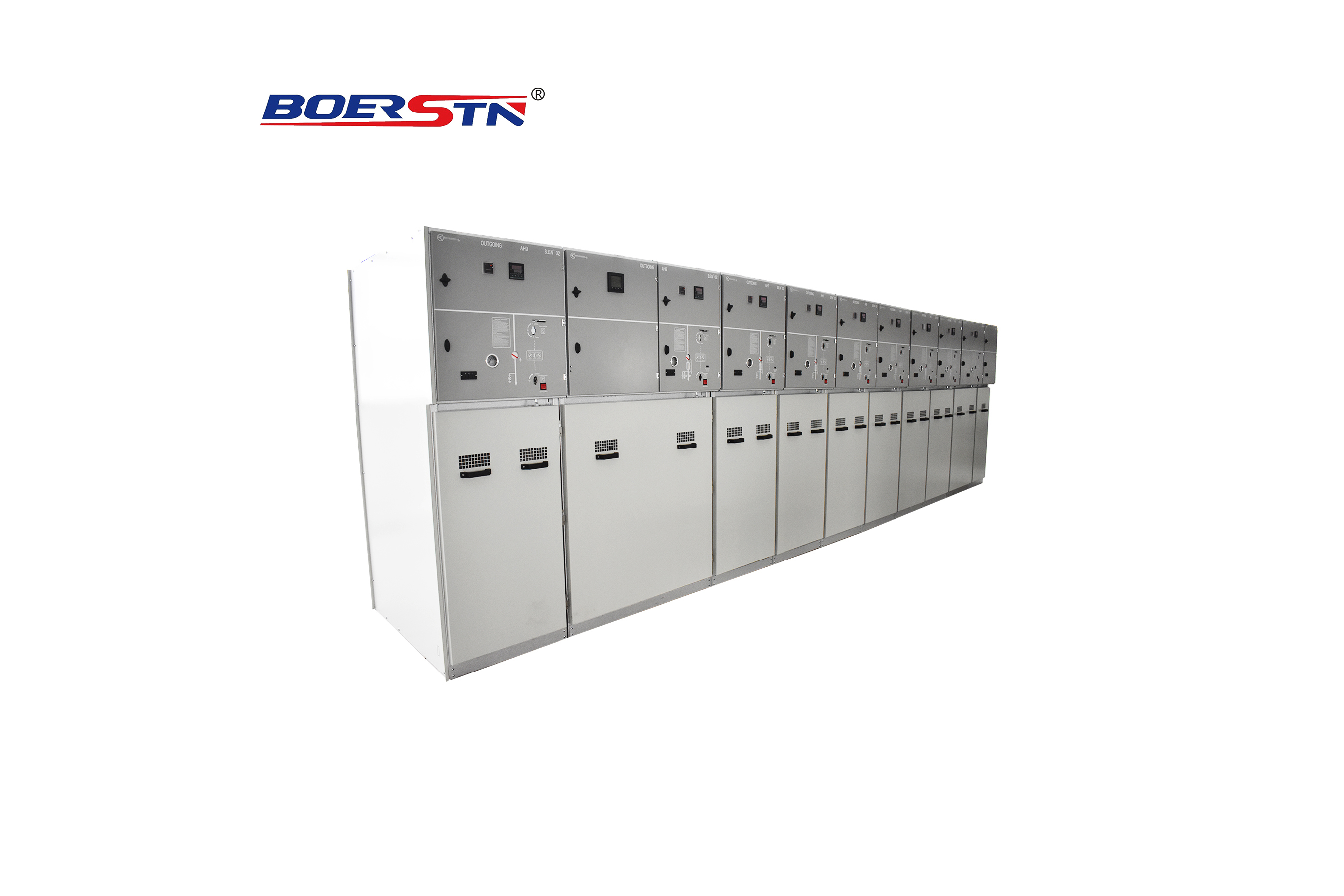
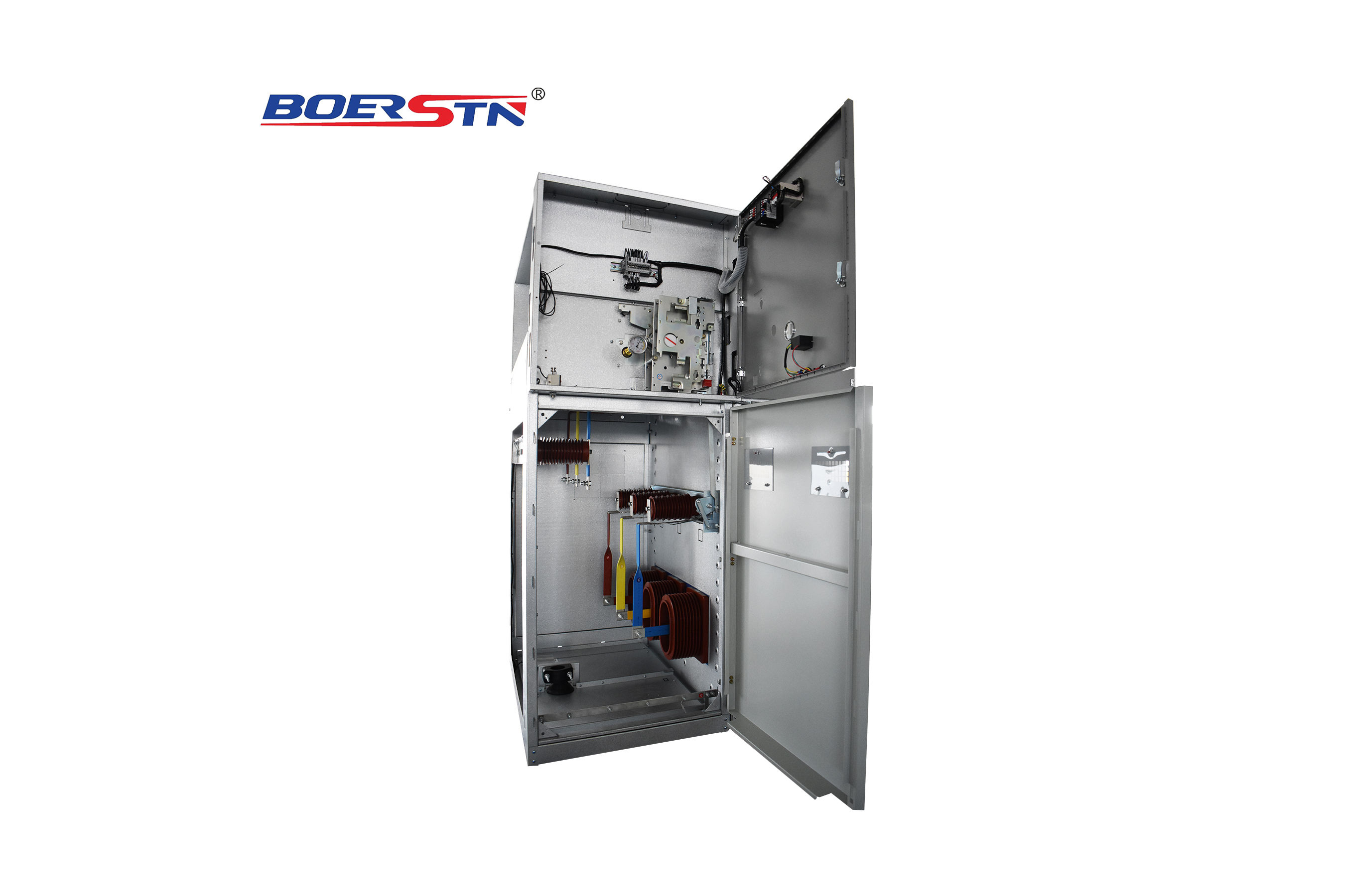
Convenient Installation

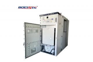
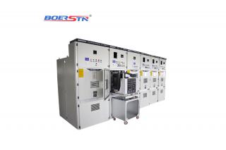
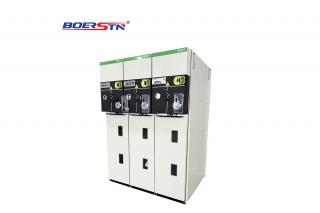
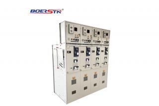
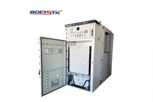
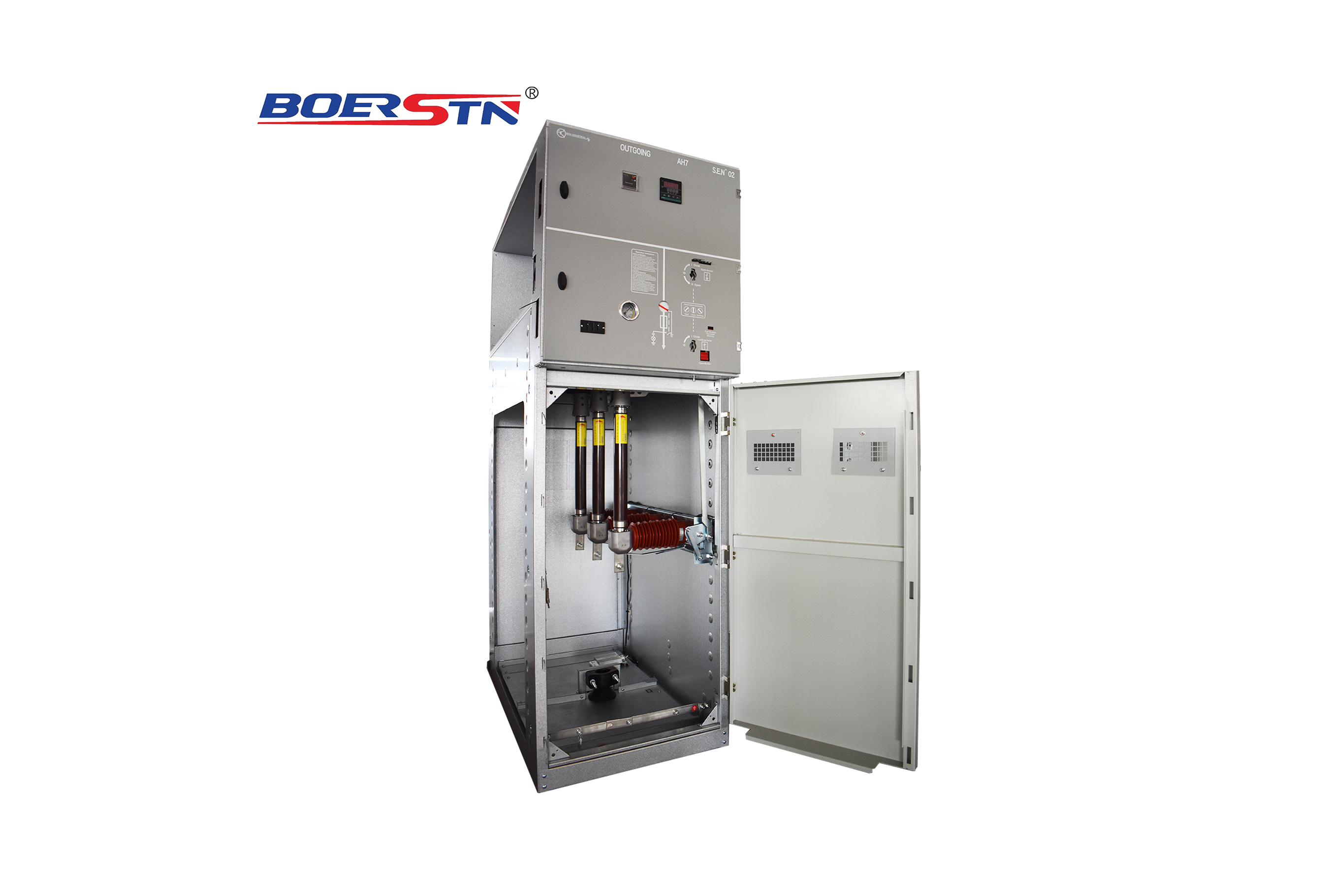
  • Its small volume & light weight make user to install & delivery it more conveniently and easy . It can be completed wiring schemes according to user’s need, also can choose the intelligent control units to realize intelligent controlling & operation. Standard design make this product to be the best choice of users.

Simple operation

  • Each switchgear has single line diagram(SLD) & analog displayer which can display inside parts. For operation, it has interlock board to guarantee the handle direction of rotation with correct operation. In order to avoid the operation in mistake, on the door, there has operation manual to supply & guarantee the simple & safe operation.

Model

Structural Features

  • Its enclosure ,door & the upper chamber is spray processing. All cabinets have main grounding busbar which can connect near cabinet. All the metal parts, like grounding switch & interlocking parts are connected with grounding busbar. In order to ensure the continuity, between the parts which connected by screws ,the connection is used by copper braid. On the back of cabinet,there has pressure relief door to ensure the gas release from the back to avoid inner burning arc. Its upper board is fixed by screws. So it can be opened from outside to connect bus. Its upper auxiliary devices chamber can be installed with terminals and other parts. After heighten the small chamber, it can realize the relay protection. The load break switch & grounding switch adopts block type interlock. The grounding switch & door adopts coercive interlock .Following below steps ,it can realize automatic interlock: close the door, turn on the grounding switch and close the load break switch. This separately operation can avoid fault.

Safe operation of HXGN15 series switchgear

  • ●Its professional structure design to guarantee its operation safety.
    ●The whole switchgear is divided into 5 insulation intervals.
    ●The interlock structure is reliable, simple and convenient.

Structure Features

  • Appearance: its enclosure is used by cold –rolled steel or aluminium zinc plate mold. It is beautiful and high anti-erosion, compact ,small volume and convenient combination.The inner has five insulation intervals. The rear side has two pressure release exits.

  • Convenient installation: it can be assembled freely & simply as different design requirements. No special need for its installation size.

  • Maintenance –free: Good sealing,SF6 insulation gas pressure complies with IEC60298 standard, safe and reliable working, maintenance free.

Design advantages

  • Pressure release :
    There have two pressure release exits for bus room & cable room to ensure the pressure release under the condition of extreme to ensure person safety .

  • Three position/double position:
    Natural interlock switch, only in “Close “,”Earthing “ or “Interlock” 3 position

  • Interlock position:
    Switch is interlocked with operation structure to avoid misoperation High voltage cable room is interlocked with operation structure to avoid opening the installation door under the condition of switch non-grounding to protect person safety.

  • Panel Display:
    Panel analog primary circuit and clearly display that charge display can flash to display the electric parts. Five independently intervals to avoid the accident spread.

Independent interval:


The five chambers are separated individually to prevent accidental accidents from spreading
① Bus interval
② Switch interval
③ Operation mechanism interval
④ Low voltage interval
⑤Wire connection interval

Main technical parameter

No.

Item

Unit

Parameter

1

Maximum system voltage

kV

12

15

24

40.5

1

Rated voltage

kV

7.2、11

13.8、15

17.5、20、22

30、33、36

2

Rated current

A

630/1250

3

Rated frequency

Hz

50/60

4

1min Power frequency withstand voltage

Phase to phase, phase to earth

kV

42

48

55

85

Fracture

kV

48

55

65

95

5

Lightning impulse withstand voltage

Phase to phase, phase to earth

kV

75

90

125/150

170

Fracture

kV

85

105

150/160

185

6

Short time withstand current

Main circuit

kA

25/2s

Earthing circuit

kA

25/2s

7

Rated withstand current (peak)

kA

63

50

8

Rated transferring current

A

1300-1700

9

Rated load circuit making current

A

630

10

Rated cable(line) charging breaking current

A

50/10

11

No load transformer breaking current

A

20

12

Cable charge breaking current in earthing fault

A

100

80

13

Rated short circuit breaking current (peak)

kA

20

14

Rated short circuit making current (peak)

kA

63

50

15

Protection level


IP4X

16

Load break switch life

times

5000

17

Earthing switch life

times

5000

Service Conditions

  • 1. Ambient temperature:-30℃ ~ +50℃;
    2. Altitude: Not exceed 2500m above sea level;
    3. Ambient humidity: Daily average RH ≤ 95%;
    Monthly average RH ≤ 90%
    4. Water vapor pressure:Daily average RH ≤ 2.2kPa; Monthly average RH ≤ 1.8kPa;
    5. Ambient environment: no fire, explosion danger, serious pollution, chemical corrosion and severe vibration place

Scheme selection

Incomer and Outgoing : (F)
Fuse combination electrical cabinet :(F·R)
Metering cabinet :(F)

Wire-Connection requirement & size

The 3 cores cable connection by making cable terminal lug.
The cable connection on the bottom through cable duct or base.

Foundation and cable trench size requirements :
The foundation shall be made of l50 × 50 × 50 angle steel or 18 channel steel ;
The width is 900 mm, and the length is determined by the combination size of the cabinet body;
The width of the cable trench shall ≥ 600mm, and the depth shall ≥800mm

The construction of cable duct requirement

Feedback form contact with us
Related Product
High Voltage Withdrawable Switchgear KYN61-40.5KV
Main characteristic 1. Cabinet structure adopts assembly type, circuit breaker adopts handcart floor type structure; 2. Fit...
High Voltage Withdrawable Switchgear KYN28A-12/24KV
Product description KYN28A air-insulated metal-clad withdrawable switchgear (hereinafter as “switchgear”) is a necessary indoor po...
High Voltage Fixed SF6 Ring Main Unit(RMU) BRSM6-12/24/40.5KV
Product description BRSM6 series SF6 ring main unit is SF6 switch as the main switch and the entire unit adopts air insulated, sui...
High Voltage SF6 Gas Insulated Switchgear(GIS) BRM6-12/24/40.5KV
Product description BRM6 series gas insulated compact type metal enclosed switchgear (hereinafter GIS ) is our introducing of fore...
Product Catalog