ZN63A(VS1)-12~24KV Indoor Vacuum Circuit Breaker (VCB)
This technical specifications is suitable for ZN63A(VS1) indoor AC medium voltage vacuum circuit breakers with spring operation mechanism. It is used for 3-phase 50/60Hz 12~24KV electrical system for protection & controlling.
Share This Product:
  • PRODUCT DETAILS
  • Testing Method

Product description

  • This technical condition specifies the ZN63A(VS1) indoor AC medium-voltage vacuum circuit breaker in terms of service conditions, rated parameters, technical requirements, test methods, inspection rules and requirements for packaging, transportation and storage, etc .In addition to meet the national standard IEC62271-100 “AC high-voltage circuit breaker”, the circuit breaker shall also meet the requirements of this technical condition.

Standard

  • The following standards contain provisions which, by reference in these technical conditions, constitute the technical conditions. At the time of the development of these technical conditions, the standard versions shown are valid versions. All standards are subject to revision and the possibility of reference to the latest version of the standard shall be considered in the use of these technical conditions.

  • (1)IEC62271-100 《3.6~40.5kV Indoor AC H.V.Vacuum Circuit Breaker》
    (2) IEC62271-100/GB156-1993 《Standard Voltage》
    (3) IEC62271-100/GB/T762-1996 《Standard Current》
    (4) IEC62271-100 《AC H.V.Circuit Breaker》
    (5) IEC62271-100/ GB/T11022 -2011 《 Common Technical Requirements for High Voltage Switchgear and Control Equipment Standards》
    (6) IEC62271-100/ DL/T593-2015《Common Technical Requirements for High Voltage Switchgear and Control Equipment Standards 》
    (7) IEC62271-100/ DL/T403-2000 《10-35KV High Voltage Vacuum Circuit Breaker Order Technical Conditions》
    (8) IEC62271-100 /GB311.1-2012 《Insulation Coordination of High Voltage Transmission and Transformation Equipment 》
    (9) IEC62271-100 /GB/T16927.1~2-1997 《High Voltage Testing Technology 》The First Chapter :General Test Requirements
    (10) IEC62271-100 /GB7675-1987 《Open and Close Capacitor Bank Test for AC High Voltage Circuit Breaker 》
    (11) IEC62271-100 / GB3309-1989 《Mechanical Test of High Voltage Switchgear at Room Temperature》
    (12) IEC62271-100 /GB9089.1-1988 《Outdoor Electrical Facilities in Harsh Conditions 》

Environment Temperature Requirements

  • a .Ambient air temperature: -55℃ to +40℃,The average daily temperature is not more than 45 ℃
    b .Average relative humidity: ≤95%;The average daily water vapor pressure shall not exceed 2.2kPa;The average monthly relative humidity shall not exceed 90% ;Monthly mean vapor pressure shall not exceed 1.8kPa.
    c The altitude:≤2000m
    d The surrounding air is not visibly contaminated by dust, smoke, corrosive and flammable gases, vapors or salt mists
    e The amplitude of induced electromagnetic interference in the secondary system shall not exceed 1.6kV

    Note: products or solutions that deviate from normal operating conditions can be customized with the manufacturer.

Rated parameters

Table 1. Technical parameters of ZN63A(VS1)-12/24kV high voltage ac vacuum circuit breaker


No.

Item

unit

Parameter

1

Rated Voltage

kV

12

24

2

Rated Frequency

Hz

50/60

3

Rated lightning impulse withstand voltage(peak)

kV

42

55

4

Rated  power frequency withstand  voltage (1s)(Effective)

kV

75

125

5

Rated short-circuit breaking current

kA

20、25、31.5、40

6

Rated current

A

630、1250、1600、2000、2500、3150

7

Rated peak withstand current

kA

50、63、80、100

8

Rated short time withstand current

kA

20、25、31.5、40

9

Rated short circuit continuous time

s

4

10

Rated short-circuit on/off current

kA

50、63、80、100

11

Percentage  of  the  dc component  of the  rated  short-circuit  breaking  current

%

35

12

Rated operation sequence


O-0.3s-CO-180s-C
O-180s-CO-180s-C(40kA)

13

Rated single/back-to-back capacitor bank breaking current

A

630/400

630/400

630/400

800/400

14

Rated short-circuit current breaking

times

50

50

50

30

15

Mechanical life

times

10000

16

Rated opening/closing operation voltage

V

AC/DC110  AC/DC220

17

Rated voltage of energy storage motor

V

AC/DC110  AC/DC220

18

Power frequency withstand voltage of secondary circuit

V

2000

Table 2. Parameters for spring operation mechanism

No.

Item

unit

Parameter

1

Rated operation voltage

Closing tripping coil

V

AC/DC110  AC/DC220

Opening tripping coil

2

Working current

Closing tripping coil

A

1.1

Opening tripping coil

3

Power of energy-storage motor

W

70、80

4

Working voltage of energy-storage motor

V

AC/DC220

5

Motor energy storage time

S

≤15

6

Aux.contact

pair

6NO,6 NC

Breaking capacity

AC/10A;DC/5A

Rated Parameters

  • In addition to meet the requirements of the design drawings, the assembled and adjusted circuit breakers shall also meet the requirements listed in table 3.

Table 3.Mechanical parameters after adjust the circuit breaker

No.

Item

unit

Parameter

1

Contact open distance

mm

11±1

2

Contact trip

mm

3.5±0.5

3

Average opening speed

m/s

1.1±0.2

4

Average closing speed

m/s

0.6±0.2

5

Contact closing bounce time

ms

≤2

6

At the different period of 3-phase consistency

ms

≤2

7

Opening time (under the rated operation voltage )

ms

≤50

8

Closing time( under the rated operation voltage)

ms

≤100

9

Primary resistance

Rated current

mW

630A

1250A

1600A

2000A

2500、3150A

Fixed type VCB

≤45

≤40

≤35

≤30

≤25

Withdrawable type VCB

≤50

≤45

≤40

≤35

≤30

10

Closing Spring energy-storage time

s

12

  • 6.1 Assembly adjustment inspection shall be carried out according to the product drawing and this technical condition, and shall meet the requirements of article 5 of this technical condition.

  • 6.2 Mechanical operation test shall be conducted in accordance with IEC62271-100

    6.2.1 Rated operating voltage shall be applied to the motor, closing tripping electromagnet and opening tripping electromagnet. Five times of closing spring energy storage and closing / opening operation shall be carried out. The operation shall be normal and meet the requirements of article 5 of this technical condition.
    6.2.2 Manual closing spring energy storage, manual button closing, operating 5 times, the action should be normal.
    6.2.3 The rated operating voltages of 85% and 110% are respectively applied to the motor, and the closing spring energy storage operation is carried out for 5 times respectively, meeting the requirements of article 5.2 of this technical condition.
    6.2.4 Rated operating voltages of AC 85%, DC 80% and 110% are respectively applied to the closing and tripping electromagnet.
    6.2.5 The rated operating voltages of 65% and 120% are respectively applied to the opening electromagnet,operate 5 times respectively and the action should be normal.Rated operating voltage of 30% shall be applied to the opening operation for 3 times consecutive and the circuit breaker shall not be tripping.
    6.2.6 One time automatic reclosing operation. Operate O-0.3s-CO for 5 times under the rated voltage and the action shall be normal.
    6.2.7 Mechanical interlock test for closing operation : The circuit breaker is in the closing position , the spring of closing is in the condition of energy-storage, push closing by manual for 3 times, the closing spring shall not be be released.

  • 6.3 Main circuit resistance measurement According to the standard IEC 62271-100. Before /after the mechanical life test and before/ after the temperature rise test, test it one time respectively and the measured value shall conform to the provisions of table 3.
    For the temperature rise test before mechanical life test, the difference between the resistance of the main loop measured after the test when the sample is cooled to the ambient air temperature and that measured before the temperature rise test should be less than 20%.

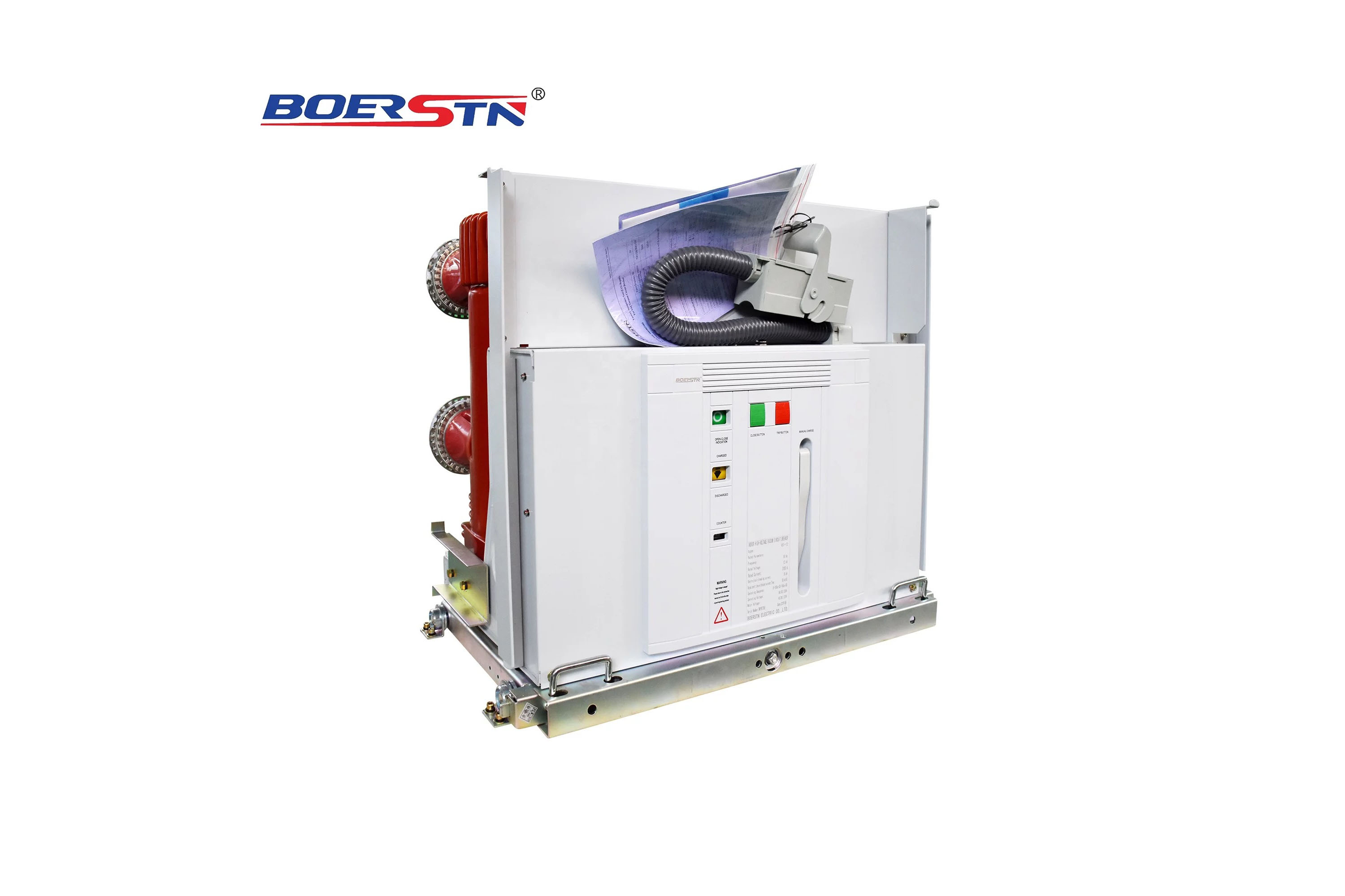
  • 6.4 Temperature rising test.

    According to the standard IEC 62271-100.
    6.4.1 Before and after the mechanical life test ,test it one time respectively. The temperature rise of the current-carrying conductor in the vacuum arc extinguishing chamber is not measured.
    6.4.2 The rated voltage is applied to the solenoid coil of the opening /closing /tripping of the operating mechanism. 10 times of continuous closing and opening is applied, and the time interval between the two electrification is 10s. The temperature rise of each coil is measured by the resistance method, and the temperature rise shall not exceed 65K.

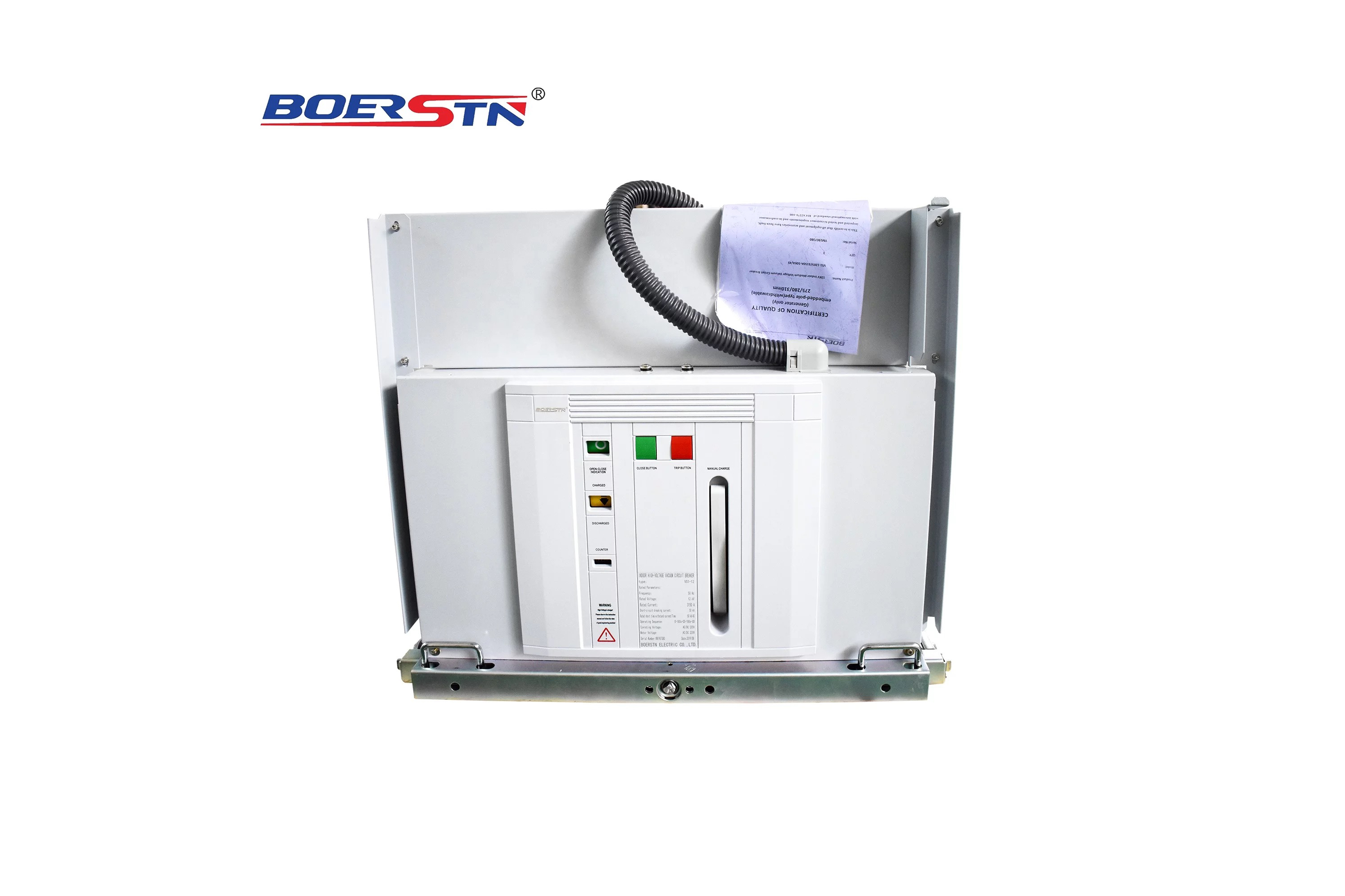
  • 6.5 Insulation Test.

    6.5.1 Power frequency withstand voltage test and lightning impulse withstand voltage test shall be conducted in accordance with IEC 62271-100, and the test voltage shall be in accordance with table 1.
    6.5.2 The insulation test of the auxiliary circuit shall be conducted in accordance with the provisions of IEC 62271-100, and the power frequency test voltage for 1 min on the ground shall be 2000V.
    6.5.3 For inter-turn insulation test of various coils in the operating mechanism, the rated voltage of the DC coil is 2.5 times 1min, and the rated voltage of the AC coil is 3.5 times 1min.
    6.5.4 The insulation of the energy storage motor shall be measured with a 500V megohm meter, and its ground resistance shall be greater than 0.5 megohm.

  • 6.6 Short-circuit breaking & on/off test is in accordance with the provisions of IEC 62271-100

  • 6.7 Rated short-circuit breaking current & breaking times test. The total breaking times of rated short-circuit breaking current is 50 (30) times, including 20 (12) times of single breaking, 15 (9) times of combined breaking, and 5 (3) times of rated operation sequence. When the breaking times test and breaking and on/off ability test are combined, the breaking times of test mode 4 and test mode 5 are included in the rated breaking times of short-circuit breaking current. 6.9 After the rated short-circuit breaking, on/off capacity and rated short-circuit breaking current breaking times test, power frequency and lightning impulse withstand voltage test shall be carried out on the fracture in accordance with GB/T16927.1, and the voltage withstand value shall not be lower than the value specified in table 1.

  • 6.8 Short-time withstand current and peak withstand current test Is in accordance with IEC 62271-100.

  • 6.9 Open and close capacitor bank test(Suitable for circuit breakers with this requirement)is in accordance with IEC 62271-100.
    6.10 Step out breaking,open/close testing (Suitable for circuit breakers with this requirement)is in accordance with IEC 62271-100.

  • 6.11 Breaking test for non-phase ground fault:The user negotiates it with the manufacturer. According to IEC 62271-100.

Type Testing & FAT (Factory Acceptance Test)

  • Type test shall be carried out in accordance with all items specified in article 6.1~6.10 of this technical condition.

  • The FAT shall be carried out in accordance with the items specified in articles 6.1, 6.2 and 6.4 of the technical conditions and the power frequency voltage withstand test specified in article 6.6.1.

  • When the design, process, key materials and components are changed, the corresponding items should be type tested.

  • Type test should be carried out when manufacture it in another factory.

Marking, packaging, transportation and storage

  • 8.1 Name Plate includes below:
    a Manufacturer name;
    b model name of breaker ;
    c Rated voltage kV;
    d Rated current A;
    e .Rated short-circuit breaking current kA;
    f Rated operation sequency ;
    g. Rated operation voltage V;
    h. Weight kg;
    i Breaker series No.;
    j Manufacturing time

  • 8.2 Package
    8.2.1 .When leaving the factory, each breaker shall have the qualification certificate, FAT test report, packing list and installation instruction.
    8.2.2 The breaker should be in the state of opening and complete release of energy when pack it.
    8.2.3 The breaker must be firmly fixed in the box, and the packaging should ensure that the product will not be damaged during transportation.
    8.2.4 The packing cases(boxes) must be rainproof and moisture-proof, and the outer surfaces of the cases shall be marked with such marks or words as "fragile", "upward", "fear of moisture", "center of gravity" and "hoisting from here".
    8.2.5 Products shall not be subject to strong vibration and collision during transportation and loading and unloading.
    8.2.6 Products should be stored in ventilated, dry and non-corrosive gas room.

Feedback form contact with us
Related Product
ZN85-40.5KV Indoor Vacuum Circuit Breaker (VCB)
The use of environmental conditions Altitude: ≤2000m; Air temperature: -55℃ ~ +45℃; Relative humidity: daily average is not mo...
36KV Indoor High Voltage SF6 Gas Load Break Switch (LBS)
Product description BRFLN36 series indoor high-voltage SF6 load break switch, It is widely used in 36kV electric power distributio...
12KV/24KV Indoor High Voltage SF6 Gas Load Break Switch (LBS)
Product description BRFLN36 series indoor high-voltage SF6 load break switch, It is widely used in 11~24kV electric power distribu...
BRCKG5 High Voltage Vacuum Contactor 13.8KV
Overview BRCKG5-13.8 AC vacuum contactors (hereinafter referred to as: contactor) are applied in power network with AC frequency o...
Product Catalog