BRCKG5 High Voltage Vacuum Contactor 13.8KV
BRCKG5-13.8 AC vacuum contactors (hereinafter referred to as: contactor) are applied in power network with AC frequency of 50/60Hz, rated voltage of 13.8kV
Share This Product:
  • PRODUCT DETAILS
  • Installation and Maintenance

Overview

  • BRCKG5-13.8 AC vacuum contactors (hereinafter referred to as: contactor) are applied in power network with AC frequency of 50/60Hz, rated voltage of 13.8kV, and rated current below 800A in the main loop for the remote making and breaking, frequent start and control of AC motor. It is advisable to use them in combination with fuse and protective device to replace vacuum circuit breaker.

Ambient Conditions for Use

  • 1 Ambient air temperature is neither higher than +40℃ nor lower than -10℃;
    2.2 Altitude of installation site does not exceed 2000m;
    2.3 The maximum mean monthly relative air humidity is 90% in the wettest month. The minimum mean monthly temperature is 25℃, with consideration of condensation generated on the surface of product due to temperature change.
    2.4 The operating condition shall be free from obvious impact and vibration;
    2.5 The medium is without explosion danger, and in the medium there is no gas and dust (including conductive dust) sufficient for corroding metal and destroying insulator.
    2.6 The operating condition shall be free from rain and snow.

Model No. & Specification

  • Composition of model No. and meanings:

For product specifications, rated voltages are 13.8kV, the rated current is below 800A. Control voltages include 220V, 380V

Structure and Operating Principle

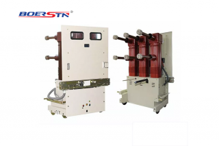
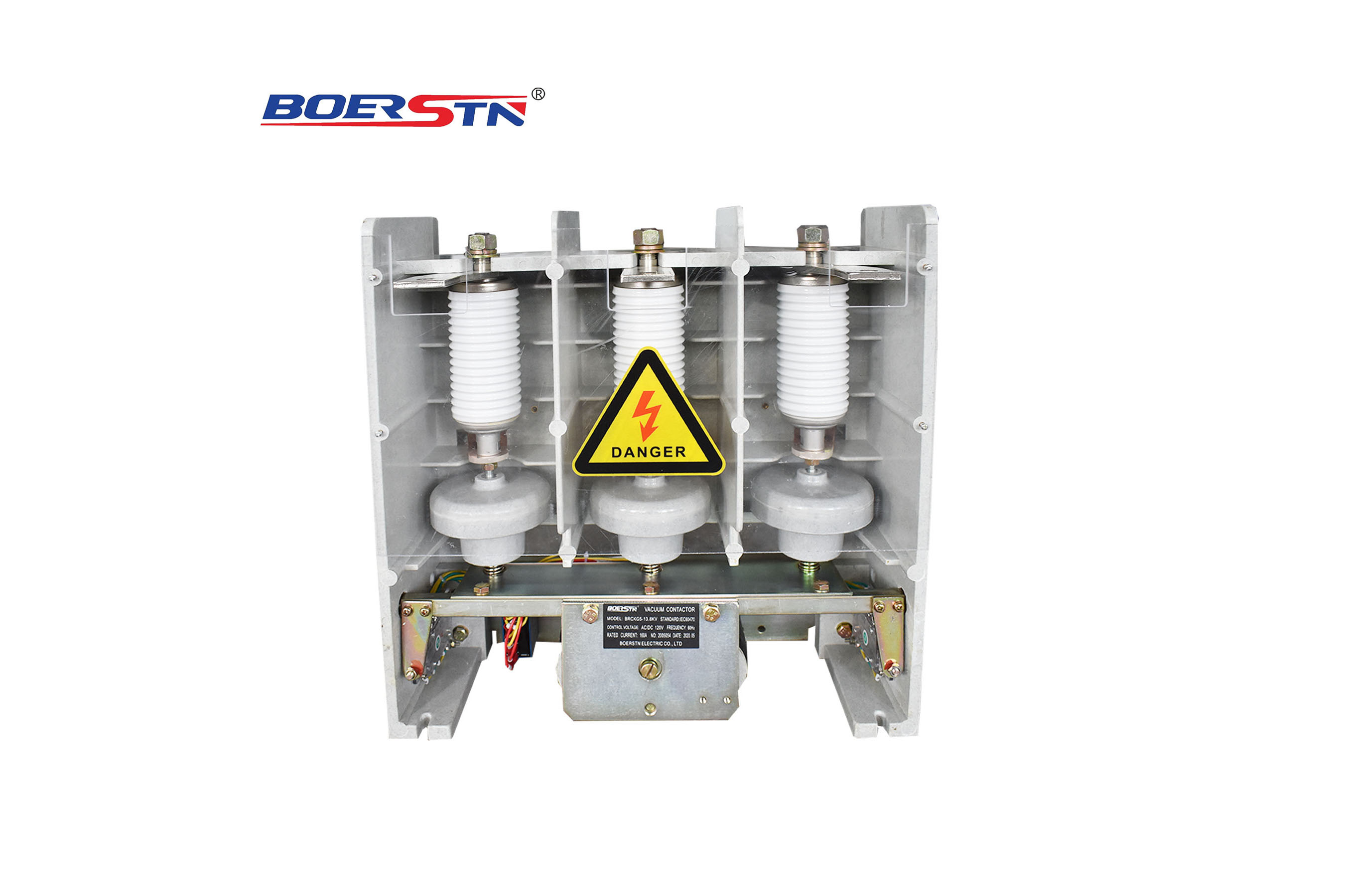
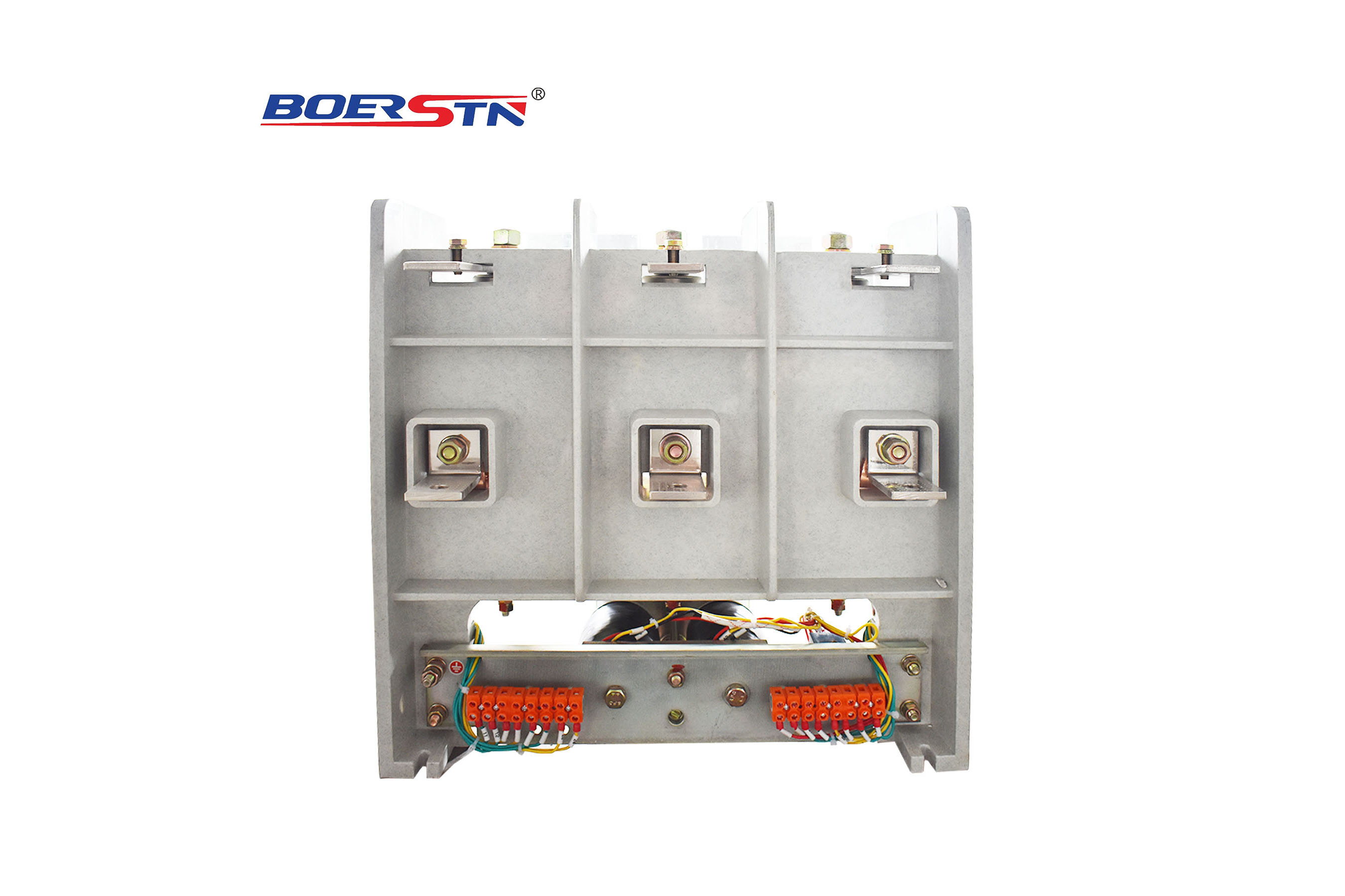
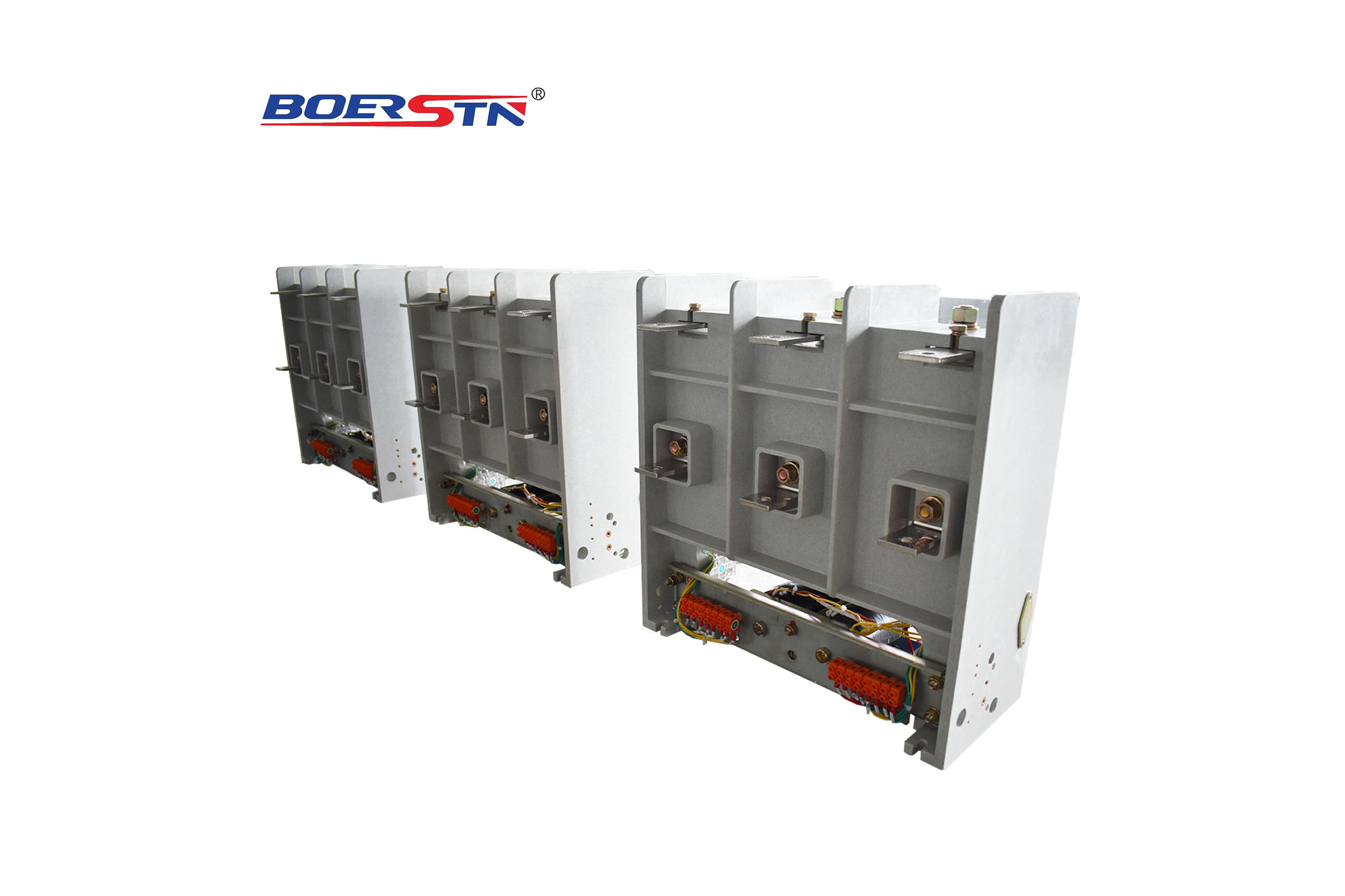
  • The contactor consists of base frame, electromagnetic mechanism and vacuum interrupter. Electromagnetic mechanism switches vacuum switch tube via armature, connecting lever and draw bar. Magnet coil is powered on when connected to control power supply. Armature drives connecting lever rotate when closing, causing the moving contact and fixed contact in vacuum interrupter to close up, and the break spring is compressed with energy stored. After closure of moving contact and fixed contact, auxiliary switch connects holding winding in series in the starting winding loop, to throttle the coil and keep magnet closed. If control power supply is disconnected, electromagnetic mechanism is powered off, and break spring is released to separate main contact and main loop breaks.

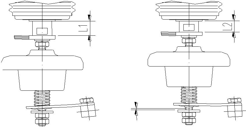
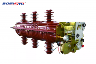
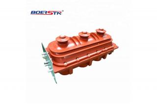
  • Vacuum interrupter is composed of upper cover, lower cover, metal bellows and ceramic tube. Its enclosure adopts corrugated porcelain tube made up of 95 ceramic. The porcelain tube features long creepage distance, high mechanical strength, heat resistance, impact resistance, etc. A pair of moving contact and fixed contact is sealed in vacuum interrupter. Contact material is Cu - W - Wc, which is of ablative resistance and low diversion closure value. In this way, if the interruption conditions are met, overvoltage caused by cut-off can be reduced in the interruption, so that service life of electric contact can be lengthened. Metal bellows drive moving contact to switch on and off while axially moving.

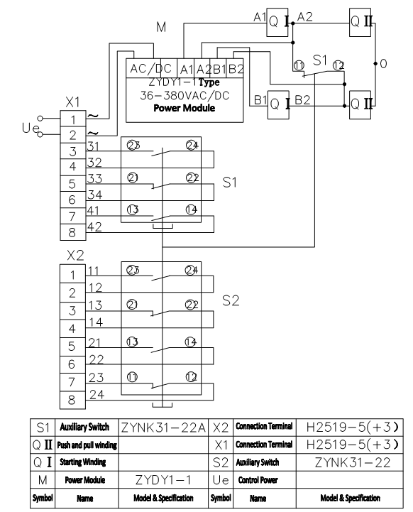
  • Considering advantages such as good coordination between actual attractive force and spring force characteristics, low-noise and energy saving, DC double coil, made up of starting winding and holding winding, is used for electromagnetic system, which is switched via auxiliary switch. In order to facilitate users to operate AC power supply, contactor is equipped with bridge rectifier.

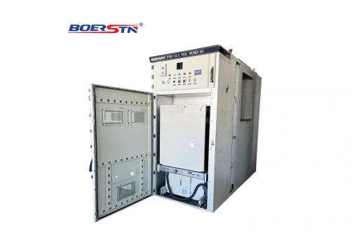
  • Mechanical padlock can be selected. When closing coil is charged, contactor is closed and mechanical padlock is locked. When trip coil is charged, mechanical padlock is tripped, and contactor is released. In thermal state, if voltage of trip coil is within 85% -110% of its rated voltage, contactor can be reliably released.

Main Technical Parameters

  • 1.Overall and installation dimensions (See Fig.1,2)
    2.See Table 1 for main technical features;
    3.Number of pole of main loop is 3;
    4.Control power supply: 220V, 380V and 50Hz/60Hz, and also customized according to user needs;
    5.Control loop is DC electromagnet. Coils are connected with AC control power supply via power module. Schematic diagram and wiring diagram (See Fig3);
    6.Rated duty: discontinuous long-time duty and repeated short-time duty (rated on-load factor is 40%);
    7.The auxiliary contact is three normally open and normally closed two, vheating current is 5A

Installation:

  • 1.1Mounting hole is drilled on mounting plate based on dimensions in Fig. 1,2;
    1.2It shall be fixed with M8 bolt and lock washer, mounting inclination not exceeding 15 degrees;
    1.3Wires of control power supply and auxiliary contact are properly connected to secondary input terminal;
    1.4Copper busbar is properly connected to main loop.
    1.5Operating voltage and current of main loop and control loop of contactor shall be in accordance with the specifications, in avoidance of damage;

  • 1.Check if the appearance is damaged. If so ,should stop the usage
    2.Clear and get rid of the dirt on its face because of transport of other reasons
    3.After installation well ,must be sure that the load switch in off position. If so, insert the operation handle into the grounding holes on its upper board ,then rotate clockwise 180 to switch on the grounding. Anti-clockwise 180 to off the grounding.
    4.When go to do the work of switching –on, firstly let the load switch be off position, then insert the operation handle into the operating hole of the load switch in lower board
    5.Operating From switch-on to switch off, For K type spring institution: insert the operation handle into the hole of load switch, anti-clockwise rotate 180 to do the off-switch.
    For A type spring institution, push the switch-off button to off the switch. Inspect the switch position through its viewing window, and watch its indication comply with the requirements or not.

Check and adjustment

  • 2.1For contactor in service, its vacuum degree shall be checked once every half a year (power frequency withstand voltage method). Power frequency withstand voltage of vacuum interrupter of 7.2kV shall be more than 15kV;
    2.2Routine check, lubrication and cleaning are performed once a year.
    2.3Check if auxiliary contact is well contacted. In case of bad contact, it shall be maintained or replaced;
    2.4After operating for 100,000 times, it shall be thoroughly checked.
    2.5If vacuum interrupter is seriously damaged or burned, it shall be replaced at once. After replacement with new vacuum interrupter, contactor shall be overall adjusted. Methods: Charge electromagnetic system of contactor to close vacuum interrupter, and check interval between over-travel adjusting nut and washer with self-made insert, which shall be between 1mm and 1.5mm, with three phases being consistent. Measure the distance L1 between the plane 5 of guide sleeve on vacuum tube and the surface of flexible connector at the end of guide rod with measuring tools (inside calipers), and then interrupt and release contactor. Then, adjust separation adjusting screw, to make the distance L2 between the plane of guide sleeve and the surface of flexible connector at the end of guide rod is equal to the sum of L1 and rated separation between contacts, (while adjusting separation, three phases need to be repeatedly debugged, to guarantee synchronism of three phases), and tighten each adjusting nut, thus separation and over-travel are adjusted up (See Fig1).
    2.6 Operation tests within the following voltage range shall be performed for the adjusted contactor:
    a.Open and close the contactor for 5 times with 85% rated control supply voltage;
    b.Open and close the contactor for 5 times with 110% rated control supply voltage;
    c.If rated control supply voltage is lower than 30%, contactor must be released and try twice.

Common faults and elimination

  • Table 2 Common faults and troubleshooting

Fault

Causes

Corrective measures

Phenomenon

No closing
after
electricity

1. Power supply circuit of
coil is open;
2.Coil is open;
3.Auxiliary contact is
poor contacted;

1.Check circuits to find out
cut-off point and reconnect.
2.Replace coil.
3.Clean auxiliary contact or
replace with a new one.

Closing not
in place or
unsustainable
after
electricity

1.Control supply voltage
is lower than 85% rated
value, and closing power
is insufficient;
2.Power module is
burned out;
3.Over-travel is
excessive;
4.Movable part is stuck;
5.Normally close contact
point of auxiliary contact
is open too early;
6. Circuit of holding
winding of coil breaks;
7. Holding winding of
coil breaks;

1.Adjust supply voltage.
2.Replace power module.
3.Adjust over-travel.
4.Check locations where
spare parts stuck with each
other.
5.Adjust normally close
contact point of auxiliary
contact.(when contactor is
closing, separation between
contact points is 1.5-2mm)
6.Check circuit of holding
winding.
7.Replace coil.

Excessive
noise and
vibration of
iron core
after closing

1.Voltage of control
circuit is too low;
2.There is dirt or rust on
pole face of iron core;
3.Fix screw of iron core
is loose;

1. Adjust control supply
voltage.
2.Clean pole face, and repair
or replace if necessary.
3. Tighten screw.


Excessively
slow closing

1.Total separation is too
big;
2.Coil voltage is too low;
3.Acting force of
breaking spring is large;

1.Adjust separation
adjustment screw.
2.Adjust coil voltage.
3.Adjust acting force of
breaking spring.

Excessively
slow
releasing
after
power-off

1.Acting force of
breaking spring is too
small;
2.Movable part is stuck;

1. Adjust acting force of
breaking spring.
2.Check locations where
spare parts stuck with each
other.

Excessive
temperature
rise or
overburning
of coil

1. Voltage of control
circuit is inconsistent;
2. Coil insulation is
damaged;
3. Normally close contact
point of auxiliary contact
is not open after closing
of contactor;
4.Power module is
burned out;

1. Check voltage of control
circuit and make an
adjustment.
2. Replace with a new coil.
3. Adjust auxiliary contact.
4.Replace power module.

Breakdown
of   power
module

1. Voltage of control
circuit is inconsistent;
2. Breaking and
closing are too much
frequent;

1. Check voltage of control
circuit and make an
adjustment.
2.Operate as per instruction
manual.


Table 1 Main technical parameters

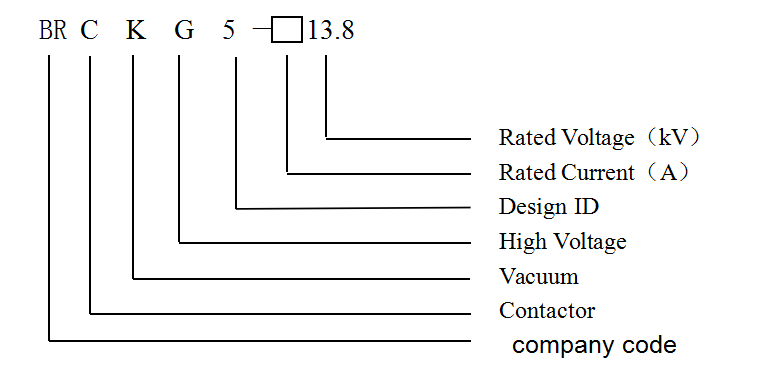
Technical Parameters      Type

Name of Parameter

BRCKG5-160-630/13.8

BRCKG5-800/13.8

160A

250A

400A

630A

800A

Main loop

Rated voltage (kV)

13.8

13.8

Rated current (A)

160

250

400

630

800

Making capacity (A/100 times)

1600

2500

4000

6000

8000

Making and breaking capacity (A/25 times)

1280

2000

3200

5000

6500

Limit breaking capacity (A/3 times)

3200

4000

4500

6000

7000

Rated power frequency withstand voltage (kV)

42

42

Service life

Electrical AC3 (10,000 times)

30

30

Mechanical (10,000 times)

100

100

Operation power supply


40

450

Closing

Starting (VA)

1000

1000

Holding (VA)

50

50

Rated operation frequency AC3 (times/h)

300

300

Short-time operation frequency times/h (20s)

1000

1000

Power frequency withstand voltage of secondary loop (kV)

2.5

2.5

Power frequency withstand voltage of control circuit (kV)

2 5

2.5

Rated operation frequency (times/h)

300

300

Operation frequency of mechanical locking (times/h)

120

120

Closing time (ms)

≤170

≤150

Breaking time (ms)

≤150

≤120

Asynchronous time of three phases (ms)

≤3

≤3

Separation between contacts (mm)

4±0.5

5±0.5

Over-travel (mm)

≥1.2

≥1.2

Resistance of main loop (μ Ω)

≤200

≤200

≤150

≤100

≤80

Terminal pressure (N)

>100

>100

>120

>180

>180

Storage and Transportation

  • 1.Contactor shall be stored in well-ventilated environment with relative humidity less than 85%, and room temperature between -25℃and +40℃.
    2.Long-term unused contactor must be regularly checked (once half a year);
    3.Working contactor shall be checked by special persons with detail records;
    4.During transportation, it is not allowed to have intense vibration and impact, and prevent rain and snow.

Order Information

  • The following contents shall be stated while placing an order:
    1.Specification & type of contactor;
    2.Rated voltage of contactor;
    3.Rated current of contactor;
    4.Control supply voltage;
    5.Quantity of contactor and that of accessories.

Breaking state
Closing state
Fig 1 Reference diagram of adjustment while replacement of switching tube
Fig 1 BRCKG8-800/7.2KV vacuum contactor and installation dimensions
Feedback form contact with us
Related Product
ZN63A(VS1)-12~24KV  Indoor Vacuum Circuit Breaker (VCB)
ZN63A(VS1)-12~24KV Indoor Vacuum Circuit Breaker (VCB)
Product description This technical condition specifies the ZN63A(VS1) indoor AC medium-voltage vacuum circuit breaker in terms of ...
ZN85-40.5KV Indoor Vacuum Circuit Breaker (VCB)
The use of environmental conditions Altitude: ≤2000m; Air temperature: -55℃ ~ +45℃; Relative humidity: daily average is not mo...
36KV Indoor High Voltage SF6 Gas Load Break Switch (LBS)
Product description BRFLN36 series indoor high-voltage SF6 load break switch, It is widely used in 36kV electric power distributio...
12KV/24KV Indoor High Voltage SF6 Gas Load Break Switch (LBS)
Product description BRFLN36 series indoor high-voltage SF6 load break switch, It is widely used in 11~24kV electric power distribu...
Product Catalog