High voltage Current Transformer (CT)
Measuring windings:The current error and phase displacement at rated frequency shall not exceed the limit values given according to the corresponding items of the standard IEC 61869-1&2
Share This Product:
  • PRODUCT DETAILS
  • Checks and maintenance

User notice

  • 1) Keep this mstruction manual in a safe and handy place in order that anyone operating or maintaining the equipment can quickly and easily refer to it when necessary. For guarantee or detail of equipment, refer to all documents concerned except the instruction manual.

  • 2) Requirement of operator : only people familiar with and skilled in handling this equipment should be allowed to operate and/or handle it.

  • 3) Please read the content concerned carefully in the instruction manual before installing, operating and maintaining the equipment. Familiarize yourself with all information of the equipment and safety precautions before using the CT, and the operate and handle it in accordance with the requirement.

  • 4) Keep the following cases from happening when using the CT:

  • a) Operate or handle the CT in any manner that is not specifically explained in this instruction manuaL

  • b) No cheeks and maintenance.

  • c) Operate the CT without transformer oil or abnormally run it.

  • d) The installation shall be carried out according to the instruction manual, don't install it in any other than the specified way. Don't use the CT in any other than the specified rating. Draft open the secondary circuits of CT for any reason whatsoever.

  • e) Don't connect or install the CT when live. All must be done by only quantified personnel to perform maintenance and checks on equipment. Don't touch live parts (including porcelain bushing). Always, open circuits and earth the main circuit before starting checks. Otherwise, it will lead to the risk of electric shock.

  • 5) If anything in this instruction manual remains unclear, please contact our company.

  • 6) If some other form of trouble occurs with the product, please contact our company in time and provide the following infbnnation. Nameplate content and specifications of the said product (Name, Serial No, lype and Date of manufacture); Description of the trouble (As details as possible, including the situation immediately before and after the trouble occurred).

Introduction

  • Type and name of the product

  • 1 Meaning of type

1. 1.2   Name: Current Transformer

1.2  Application and applicable scope

1.2. 1  Application
In the outdoor alternating current power system with a rated frequency of 50-60 Hz and rated voltage of 145kV this current transformer can be used for current measurement, electric energy measurement, automatic control and relay protection.
1.2.2  Applicable scope
a.  Altitude < 2000m
b.   Ambient air temperature: -40 ― 50°C
c.   Wind speed < 35m/s


Construction and operating principle

  • 1 Construction and dimensional drawing of the product (see fig.l) This current transformer has a hermetical structure, each sealing surface has been hermetically sealed by oil resistant rubbers. In order to ensure each of connection fastened well and not to make the gaskets compressed too much, all parts of the equipment are sealed up limitedly. The equipment is mainly comprised of metallic bellows, device body, porcelain bushing, oil tank, primary winding forms "U" type, using the insulation structure of oilpaper for capacitance type. The major insulation is sealed in transformer oil through the treatment of vacuum drying and hermetical oiling; the transformer oil used shall be fully treated through dehydration and degassing treatment. The insulation of the equipment has high electrical strength, low dielectric loss and low partial discharge. The transformation of current ratio can be carried out by the external implementation of series and parallel connections fbr primary winding terminal plate, or by the exchanged connection for secondary winding terminals, that is, measuring winding and protective winding can be tapped. Secondary windings go around the Ring Core,set in the bottom of primary winding and placed in the oil tank; secondary winding terminal box is located in the front of oil tank,oil valve for draining is located at the bottom of oil tank. Metallic bellows is installed at the top of the product, which can play a role in volume compensation when the oil temperature varies,and isolate effectively the transformer oil from the atmosphere,so that prevent the ageing of transformer oil. Metallic bellows (PB type) is made of a certain number of expansion joints welded in series, which owns the advantages of displaying direct for the oil level and reflecting sensitively for the pressure.(see fig.2)

  • 2.2 Electric schematic diagram(see fig.3) Unscrew the valve cover, oil sampling can be made by the syringe with pinhead puncturing the oil resistant rubber gasket.Get the required amount of oil and then put the cover on.

  • 2.4 Hermetical oiling You should use hermetical oiling.Before the oiling,please put clean the oil in the upper of the bellows. Then connect with the joint for vacuum-pumping when remove the core of bellows,and unscrew the valve cover at the bottom,the oiling can be carried out by the syringe with pinhead puncturing the oil resistant rubber gasket (notes,the pinhead can not exceed the type No.7).At this moment, you should open the valve for vacuum-pumping and vacuumize for 2 to 4 hours. When the vacuum degree achieves such an extent (≤133Pa),you should open the valve of the oiler at the bottom, and inject qualified transformer oil with the same brand.And keep the degasification for 8 hours when completes the oiling. 3. Main technical parameters

  • 3.1 Rated voltage:126kV

  • 3.2 Highest voltage for equipment:145kV 3.3 Rated primary current: 600-800-1200-2000A 3.4 Rated secondary current: 1A

  • 3.5 Rated transformation current:

  • Core 1,Core 2,Core 3,Core 4,Core5 600-800-1200-2000/1A 3.6 Rated frequency: 50/60Hz

  • 3.7 Polarity: Negative

  • 3.8 Accuracy class: 5P20/0.2/0.2/5P20/5P20 3.9 Rated output: 30/30/30/30/30VA

  • 3.10 Current error and phase displacement limit

  • 3.11 Measuring windings:the current error and phase displacement at rated frequency shall not exceed the limit values given according to the corresponding items of thestandard IEC 60044-1:2003,when the secondary burden is any value form 25% to 100% of the rated burden.(Notes:the secondary burden used for test purpose shall have a power-factor of 0.8 lagging)(Details in the following sheet)


Accuracy class

± Percentage current (ratio) error at percentage of rated current shown below

士 Phase d i sp1acement at percentage of rated current shown below


± (%)

土(’)

1

5

20

100

120

1

5

20

100

120

0.2

/

0.75

0.35

0.2

0.2

/

30

15

10

10

3.10.2 Protective windings: At rated frequency and with rated burden connected, the current error, phase displacement and composite error shall not exceed the limit values given according to the corresponding items of the standard IEC 60044-1:2003. (Notes: the secondary burden used for test purpose shall have a power-factor of 0.8 lagging) (Details in the following sheet)


Accuracy class

Current error at rated primary current

Phase displacement at rated pr imary current

Composite error at rated accuracy 1imit primary current


± (%)

土(’)

± (%)

5P

1

60

5

3.11 Instrument security factor for metering cores: Fs < 10

3.12 Accuracy limit factor for metering cores: 20

3.13 Limits of Temperature rise

The temperature rise of the current transformer when operating for a long term under rated primary current and rated output, shall not exceed the limiting value shown in the following.

a. Temperature rise of the windings: 65K

b. Temperature rise of the top layer of oil: 55K

c. Temperature rise of exterior terminal (Pl, P2) or interface of the windings: 50K

5. Insulation performance requirements

3.1 Short-time power frequency withstand voltage

a. Short-time power frequency withstand capacity on secondary windings and end shielding to earth: Applied voltage on winding-to-winding and winding-to-earth shall be 3 kV / 50 Hz / 1 min, and the shielding-to-earth shall be 5 kV/ 50 Hz / Imin.

b. Short-time power frequency withstand capacity between the primary windings: Applied voltage between the primary winding sections shall be 3 kV/ 50Hz / 1 min.

c. Short-time power frequency withstand capacity on primary winding: Applied voltage on primary winding to secondary windings and earth shall be 230 kV 50 Hz /I min.

d. External insulation short-time power frequency withstand capacity in dry and damp conditions shall be 230kV / 50Hz / 1 min.

3.2 Lightning impulse withstand

Full impulses: 1.2/50P-S 550 kV (Peak)


3.1 Inter-tum insulation strength

The rated withstand voltage for inter-tum insulation shall be 4.5kV(Peak).

3.2 Capacitance and Dielectric dissipation factor(tan 8 )

3.2.1 The value of dielectric dissipation factor should be referred to a voltage level in the range from lOkV to Um/V3, tan 8 <0.5%.(Um=126kV)

3.2.2 Applied voltage on end shielding to earth is 3 kV /50 Hz, tan 8 < 2%.

3.3 Partial discharges

Applied a voltage level with Um, PD < 10 pC; Applied a voltage level with 1.2Um/V3,PD

3.4 Rated short-time thermal current (Ith): 45kV/ Is

Rated dynamic current (Idyn): 126kV

3.5 Performance requirements of transformer oil

Transformer oil shall meet the requirements of the corresponding items of the standard IEC 60296:2003

Transport, storage, installation and test

5.1 This current transformer shall be foxed inside the packing box, and the transportation only can be performed after the packing is completed. The equipment injuries when dropped down or toppled over in transportation, do not transport it in any other than the specified way, and collision and other mechanical damages shall be prevented.

5.2 Transportation way: Vertically foxed to transport

5.3 When receiving packages, all packages should be inspected for their appearance based on the packing list prior to acceptance. And then unpack the box (remove the top and side plates of the package while special caution must be taken not to damage the porcelain bushing) to inspect the equipment carefully, you should check whether there are damages during transportation such as porcelain bushing broken, oil leakage or deformation and so on, and also check whether the spare parts and technical data or documents are complete. Please contact our company immediately if you find something wrong, so we can investigate the cause and properly handle it in a timely maimer. After the inspection, please return the equipment to the state in which it was transported as best possible to store the equipment safely.

5.4 The equipment shall be stored in the places with a ambient air temperature

of - 25°C〜+50°C, and there shall be no fire goods, explosive substances,

corrosivity and serious concussion. Water should be quickly and completely drained form the ground in case of outdoor storage. The equipment should be raised about 10cm above the ground by placing wooden blocks under the package for the purpose of securing better ventilation and protecting the packages and the equipment form immersion and rain. During ling-term

storage, you should check the performance of oil level and sealed condition periodically, handle it immediately if you find something wrong. The guaranteed valid period of packages of equipment is about 12 months after shipment. In case of packages to be stored after the valid period, such packages should be immediately unpacked and equipment should be properly treated by moving it inside the warehouses after making inspection.

5.5 Remove the bolts for foxing the CT to the bottom plate of the package, and fasten 4 wire ropes of same length to the lifting hooks on the oil tank (don't lift the CT on the top of it). The main wire ropes must be bound by using another rope or strap to avoid the main ropes loosening. The CT's top cover should be protected from damage by felt rings or rubber cushions. And then slowly lift the CT and move it to the supporting structure. Fix the CT by the attached mounting bolts. The hoisting shall be slowly and stably performed to prevent the action of impact force.


5.6 Examination before installation


5.6.1 Appearance inspection: Inspect the CT carefully, maybe find damage during transportation such as porcelain bushing broken, oil leaking or deformation and so on .

5.6.2 Check the performance of oil level, if the level lower than the normal line, you should add qualified transformer oil with the same brand in time.

5.6.3 Check the paint surface of metal fittings, if the paint comes off, you must touch up the chipped paint on it as early as possible.

5.6.4 Before operation, acceptance test shall be conducted according to the requirements of the contract and corresponding standard items: Insulation resistance measurement, capacitance and dielectric dissipation factor measurement, transformer oil test, volt-ampere character measurement, polarity check, current ratio measurement and so on.

5.5 Installation Notes

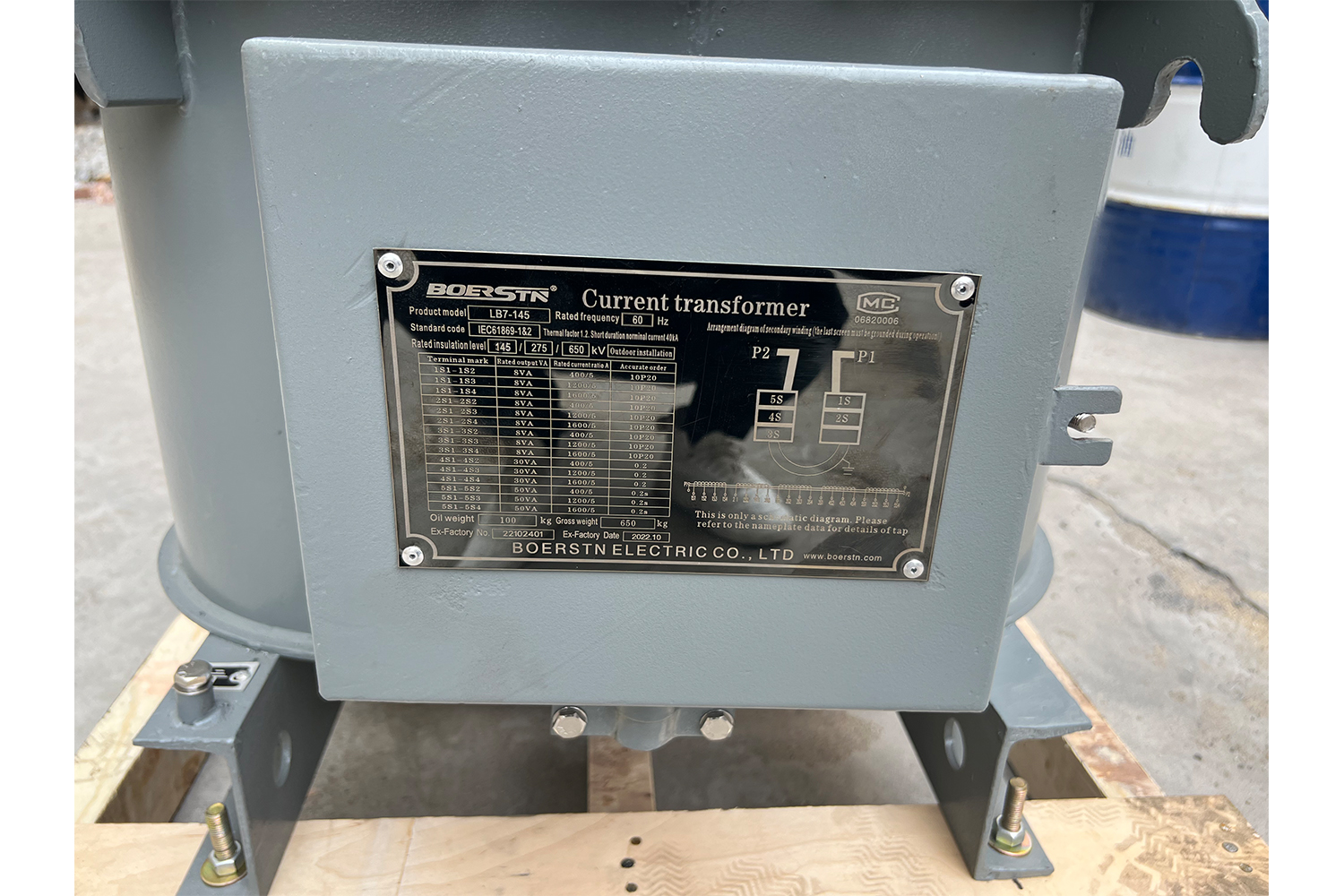
5.7.1 Before operation, the current ratio made by the connection of primary terminals in series or in parallel and connection of secondary terminals, which must be checked whether complies with the requirements of your operation. Regarding the connection methods, you can refer to the wiring diagram on the nameplate. All fixed fittings must be screwed tightly in order to preventing bad contact, which could cause a high temperature rise or secondary terminals open. If only can be allowed the connection in series or in parallel for the equipment, you should not change the primary terminal already connected.

5.7.2 The secondary leading cable must pass through the tube under the secondary terminal box (a round lid on the middle of the oil tank). The diameter of the cable shall be less than 40mm. After the cable getting through the tube should be connected with the secondary terminal, and then fasten the lid tightly. Use insulated tape to bind up the tips of the cable and fix it firmly with the clamp.

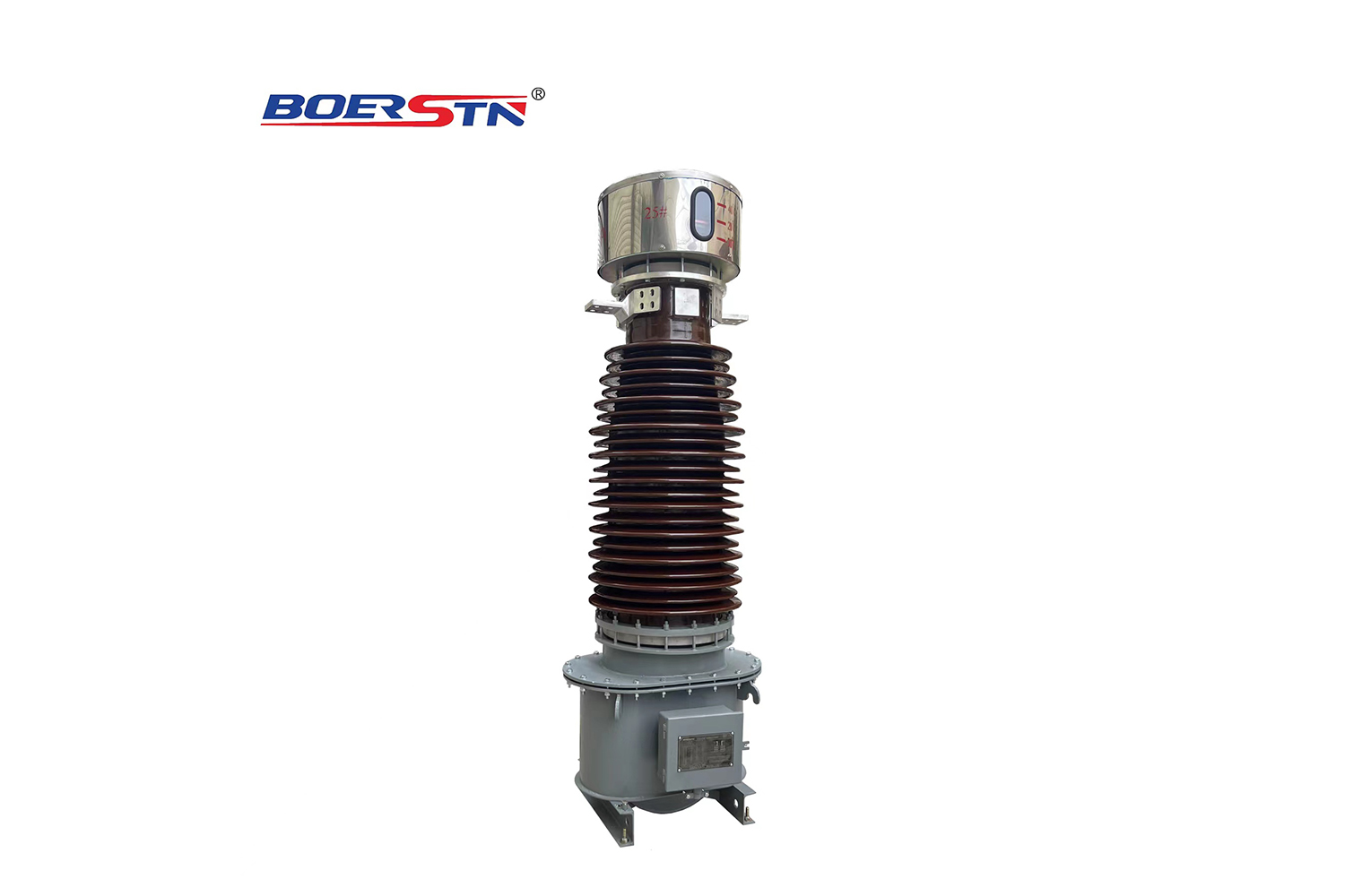
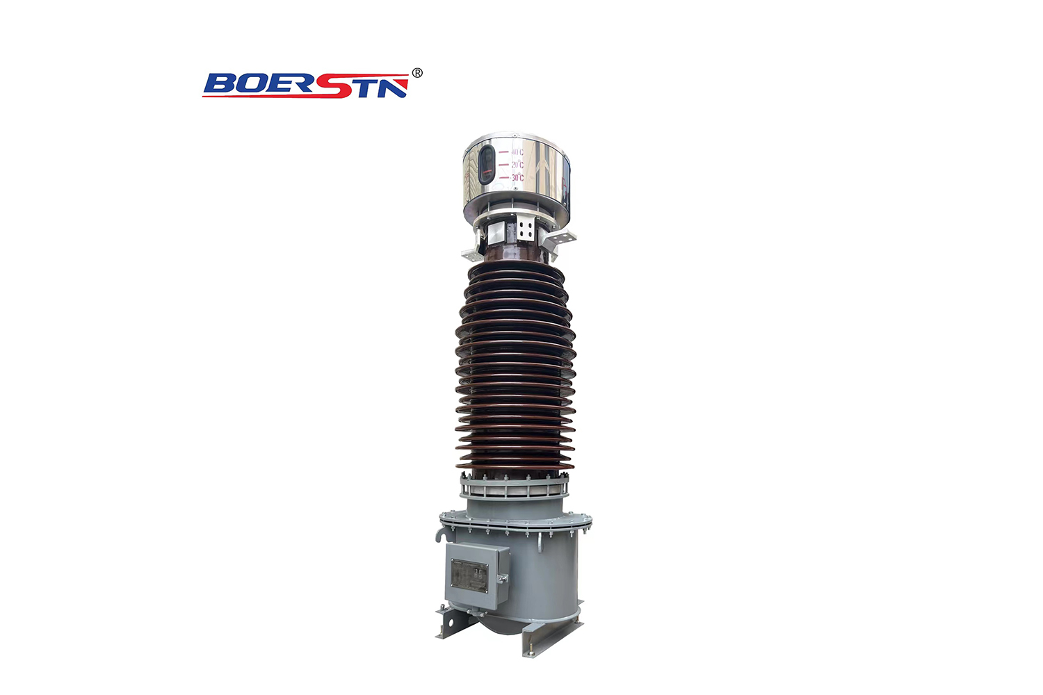
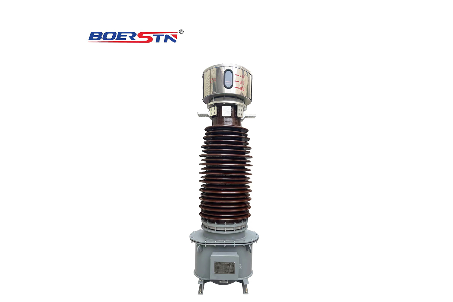
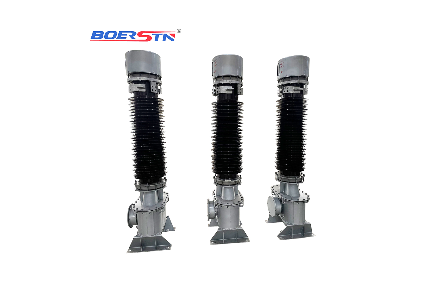
go around the Ring Core, set in the bottom of primary winding and placed in the oil tank; secondary winding terminal box is located in the front of oil tank, oil valve for draining is located at the bottom of oil tank. Metallic bellows is installed at the top of

5.7.3 Each secondary winding of the equipment shall not be allowed to open. If one of secondary winding is not used temporarily, you must make the secondary terminals to be short-circuited. The primary end shielding terminal and the earth studs on the oil tank must be earthed reliably, so that the equipment can be put into operation.


6.1 It is proposed that surveillance should be carried out during the operation.

6.1.1 Monitor the oil level indicator (placed on the metallic bellows) frequently during the operation, because the oil level varies can reflect the change of internal pressure (or temperature) of the equipment. If the oil level is low because of oil draining, you should add the qualified oil timely; if the oil level is too low, you should check the equipment and find whether there is a leakage, and add the qualified oil in time after handing the leakage; if the oil level is too high, you can drain a little amount to make the oil level matching the actual temperature; if the oil level increases abnormally and exceeds the rated route of metallic bellows, you should stop running for further investigation.

6.1.1 In the operation, the insulation preventive test shall be conducted periodically according to the requirements of corresponding standard items. Focus on the following items:

a. The variation of capacitance and dielectric dissipation factor fbr the major insulation

b. The variation of insulation resistance

c. The variation of capacitance and dielectric dissipation factor fbr the end shielding to erath

d. Chromatogram analysis and moisture content analysis of the transformer oil If abnormal circumstance happens, the follow-up inspection and analysis should be carried out in a timely manner, and if necessary, you should quit the operation fbr further inspection, testing and maintenance to prevent explosion accident due to the expansion of the failure in the operation.

6.1 Examine and repair

6.2.1 Through the gas chromatography analysis, you find the amount of gases of the transformer oil exceeds the standards. However, through the insulation test and analysis, there is no obvious defect to be found. In this case, you should give the equipment a degassing treatment. Usually speaking, the way of air-in and nitrogen-in shall be used, that is to say, remove the metallic bellows and connect to a vacuum pump fbr vacuumizing in the upper, at the same time, connect to dry air or nitrogen bottle fbr charging in the lower.

6.2.2 If the value of dielectric loss rises due to the aging of transformer oil or the transformer oil exported to moisture, you can run the transformer oil away, and heat the qualified oil (up to about 70°C), then make the thermal oil get through the inner iteration of the equipment. You should run the thermal oil away after cycling for 24-48 hours, and immediately vacuumize the equipment for 48-96 hours (notes, get and hold vacuum degree lower than 133Pa), and then carry out hermetical oiling and vacuum degassing to the equipment. Do it repeatedly until it is qualified.

6.2.3 If the value of dielectric loss is too high, and the value of dielectric loss varies sharply with the change of voltage and temperature, or the rate of gas production gets too high, you should ask for the help from the manufacturer to assistant you to cany out an inspection on the suspended core, or return the equipment to the factory to repair.


Feedback form contact with us
Related Product
145~252KV Hybrid Gas Insulated Switchgear (HGIS)
Overview 1. 1 ZHW-145 Hybrid Gas Insulated Switchgear (hereinafter referred to as HGIS) belongs to three-phase AC ...
LW36-72.5~252KV  Outdoor SF6 Circuit Breaker
LW36-72.5~252KV Outdoor SF6 Circuit Breaker
Summary LW Series self-energy SF6 Circuit Breaker is a three-pole/single-pole AC 50Hz/60Hz outdoor high voltage power transmission...
LW30-72.5~252KV Outdoor SF6 Dead Tank Circuit Breaker
Dead tank type SF6 Gas Circuit- Breaker 72.5kV up to 252KV, 25kA~63kA, 1250A~4000A for Outdoor Three phase/Si...
40.5~252KV GW7 Outdoor High Voltage Disconnector Switch
1.Application GW7-145D(W)series is a kind of three column ,horizontal/vertical,double break out-door three phases AC HV disconnect...
Product Catalog